I mentioned in the first entry on the Auto-Regulator that I would talk about how it brought me to where I am now. The short version is that the clock put me out of business. I'm still a
woodworker in heart and mind. But I won't be on my 1040 at the end of
the year.
I had this grand plan to do the full write up on the clock, and then use this news as the punchline. But the truth of the matter is that I've been very much aware of all of the writing and woodworking that I haven't been doing for the past few months, and I felt the need to say something. At the end of the day, the clock wasn't the greatest business decision. It was a lot of work. It was both challenging, and rewarding. And I'm proud of the end product. But it won't be going into production. That's as much of the story as I'm going to publish. Shutting down was heart-breaking, and a relief.
Since mid-September, I've been at home, taking care of my son. He's almost 2. He's awesome. I've sold most of the big tools. A few will be in storage for a while. I have my small bench in the basement right now, with my North Bennet Street tool chest underneath it. And I have my Festool stuff down there, taunting me. I still love wood-work with a passion. My perfectionist streak dictates that I will still reserve my love for only the very best. But I'll have to find smaller-scale projects to build and blog about, that still stimulate me, and still satisfy my perfectionist urges. I'm excited to see how tht unfolds.
In the mean-time, the toddler does his work well, and I'm pretty wiped out when he finally goes down. So the write-ups on the clock remain slow in coming. I have a couple of other projects that got done in the waning days of my business, so there's plenty to write about while I marshal my energy to be creative again, and while I get my available space organized.
My heartfelt thanks go out to all who have been reading, responding, and offering support or feedback of every kind.
James
Saturday, December 13, 2014
Tuesday, October 14, 2014
Auto-Regulator, Chapter 4: Cutting the arch, part 1

The arch, the upper side horizontals, and the vertical posts come together in a pair of 3-way miter joints at the top of the case. That's the short version. And from an aesthetic point of view, that's really the version that matters. As long as the joint is cleanly made, the eye will freely run along the lines of the case. But from a construction point of view, things are almost never that simple. If there are any gaps, voids, or other breaks in the surface, the eye stops there, and the mind will take note. Much like a shrieking saxophone or clarinet in an orchestra, it won't matter if the melody is miraculous. It's the shriek that you'll notice, and the reverie will be interrupted. So, to make those clean transitions, understanding what's going on is a huge help... and I didn't properly understand what was going on when I got started on this project. So I'm going to break down this deceptively simple looking joint, before we get into how it was done.

On the side of the clock, the vertical post meets the upper horizontal in a 45 degree miter. That's pretty straightforward. I'm going to refer to this as the side miter.
On the front of the clock, the vertical post meets the arch in another miter joint, that's cut at an angle that I've never bothered to measure in terms of degrees. Those miter lines point from the top corners of the case, directly to the center of the clock face. The inner radius of the arch is concentric with the dial, so the miter line runs radially through that edge. I'll refer to this as the front miter.
The curved top surface of the arch meets the upper surface of the upper horizontal members in a 45 degree miter. And I'll refer to this as the top miter. And this is where things start to get funky in the mechanics of the joint.
The plane of the cut for the side miter is at 90 degrees to the plane of the side of the clock. Or, the table saw blade is at 90 degrees to the table, when those miters are cut on those pieces. The cut for the front miter is also cut at 90 degrees to the plane of the surface. That's pretty straightforward. And in my head, that made everything seem very, very simple. That should have been a clue to me that something was awry, I guess. But because the face miter is cut at a different angle as the side miter, the edge where those two cuts intersect gets skewed to one side. So the three-way miter becomes a three way compound miter.

Each cut defines a planar surface. Geometrically speaking, two planes that intersect will define a line along that intersection. Practically speaking, that line defines the edge that's made where the two cuts come together. And for this joint to work, the edge defined by the two cuts made on the vertical post, the edge defined by the two cuts on the horizontal member, and the edge that's defined by the two cuts on each end of the arch... those three edges must come together cleanly along their length, with all of the mating faces coming together fully.

The test joint actually came together cleanly, but if you zoom in on the picture, and see the different surfaces interacting, you'll start to get an idea of just how many things can go wrong in the joint. Oh, and having one of these come together is hard enough. To cut the arch properly, there are two of these joints to consider, one on each end. Which brings us back to the top miter.
To cut that compound miter, the 45 you see on the surface is defined in relation to the top edge of the horizontal, and the back edge of the arch. The angle of the blade during the cut, which is what makes this a compound miter, is defined in reference to the surface of the parts that will lie flat on the saw table.
But the top is curved. There is no reference surface.
Obviously, to be continued...
Tuesday, October 7, 2014
Auto-regulator, Chapter 3: Making the vertical elements

One of the primary design elements of the case was the use of three way miters. In the pedestal, as I've explained, they're not true three-way miters. The movement case is a different story. But there's more to it than that.
Mitering an end-grain joint is a fairly straightforward affair. Typically, it's used in case constuction, and the biggest miter joints I've usually seen are on things like blanket chests. That may be up to 18" worth of miter, but it's not too hard. In this case, I had a few more variables to consider. First, the stock was re-sawn out of a larger piece. It was mostly flat, and behaved fairly well. Second, the joint has to come together flatly, and mate with the solid core. So, if there was any concavity, or convexity in the joint, I'm going to have issues, because either the middle or the ends won't mate cleanly with the core. Lastly, these pieces are long. 32" of walnut, plus extra to trim back, and 42" of maple, with extra. So they needed to be long, straight, and perfect.

Lastly, I needed everything to be dead straight. Given the thicknesses of everything involved, I wasn't too worried that things would go awry, but to be sure, I made box beams to provide flat reference surfaces for gluing, and glued everything up.

Thursday, October 2, 2014
Auto-Regulator Chapter 2: Below the Waist

I couldn't help myself when it came to naming this entry. The irony is that in this case, everything below the waist isn't where the real action is.
A note on process: I started this project with a commission to build 2 cases. One in walnut, one in curly maple. So, you'll see parts here for 2 different cases. As I went through these parts, I decided that I would separate the two cases when I went on to build the movement case. The walnut case would be the prototype, (the one where I made my mistakes) and the maple would be the first official 'production' case. Walnut's a little more forgiving to work with than maple, both in the working of it, and in the fact that minor discrepancies are more easily covered up.


The pedestal is actually rabbeted around the bottom edge, because I wanted the joint line to be horizontal. This is intended to be a production case, and this joint will not be glued. So, in the event of any gaps between the base and the pedestal, I didn't want those gaps to be visible. So, the pedestal lips slightly over the base, and seats solidly in.


Like the base, there are internal plywood frames to reinforce the structure from inside. The bottom frame is open to allow access to the adjustable feet in the base, if needed. That way, if anything settles, the clock can be leveled without having to take it all apart. (That's the theory, anyway.) The top frame is open to allow cables to pass through, and go up into the movement case. The solid wood, mitered top of the pedestal is glued to this frame, and the waist is glued to it, too.
Because the plywood frame is glued into a groove that cuts across the vertical members of each panel, the miters won't actually be supporting the weight of the case, and the movement. The vertical load of the clock will sit on the waist, which sits on top of the plywood frame, which sits in dados that lock that frame directly into the vertical members. So, while it looks like the miter joints are supporting everything, they're not. The load actually hooks into the structure just south of that top mitered panel.
So, as I said, below the waist, the case structure is fairly straightforward. That's not where the real action is.
Thursday, August 21, 2014
Auto-Regulator chapter one: Breakdown.

I suppose the first entry for this particular series should be about milling up the lumber. There are many, many instances where boards continue around corners, or where the grain continues from the movement case, past the waist of the case, and down the sides of the pedestal. There are so many individual parts to the case, that I didn't want to run the risk of having too many subtle differences in color, or texture, especially around the mitered corners. So, I cut every piece from a couple of huge beams of 12/4 walnut. Well, I tried to, anyway. In the end, I'd cut the front arch 3 separate times before I understood what was going on in the miter joint, so that's actually from a different piece of walnut.

 The diagonal grain near the top was a fluke. That's just what I happened to get when I opened up the beam... the grain went from being in-line with the board to 30-something degrees on angle from the face.
In the end, the pillars are a 3-part lamination: There's a 2 1/4" square core, which is destined to be sculpted down on the inside, faced on the outside with 3/4" thick pieces that are seamlessly mitered around that front edge. Those face pieces continue down into the pedestal, but the grain's pretty straight, so it's not so obvious at that point. And, the pedestal's not an open structure, so the solid core isn't there. (There's no need to sculpt anything, and we needed room for the clock's power supply, anyway.)
 The pedestal parts aren't solid... they're all 3/4" thick pieces that are mitered into panels, and those panels are, in turn, mitered on the edges into a box. But, adjacent pieces along the edge from side to top were contiguous in the original stock, so that had to be taken into account.
Put simply, there was a lot to keep track of when I was breaking down the 12/4 stock... what pieces were book matched, or continuous, and with what. I went through (and broke) many crayons in the process, making notes on all pieces to indicate what went with what. Front pieces for the pedestal, orientation to keep grain continuity with the movement case pillars, or to keep continuity with the upper faces of the pedestal... Not exactly a Rubik's cube, but it felt a little like that sometimes.
-----
Note on the photos: All of the pictures of the finished piece were taken by David Schonbrun.
The Auto-Regulator

This project was a monster on many fronts. There were many jigs to work out, many issues I hadn't foreseen, many, many late nights, and a lot going on at home, to boot. I haven't blogged since April because, quite plainly, I was fried, and had no time.
That's been getting better, so I'm back. In coming weeks/ months I'll go through the project from start to finish, and explain how it all came together, and how it's led me to where I am now.
Sunday, April 20, 2014
Circular Logic, Part II
Project X has been an utter monster in recent weeks. I hate calling it Project X. I'd rather come out with the name and details, but it's not my product, so I'm reluctant to say too much until it makes a debut somewhere.
In any event, this piece has required so much problem solving that it's eaten up a lot of time. Every time I solve one problem, another one pops up, if not 2. It's resulted in a lot of sleepless nights, staring at the ceiling in the dark, and trying to wrap my head around changing curves and angles, so I have a better understanding of what's going on. Then I have to figure out how I'm going to make the mental image that I come up with come together in the physical world. In theory, this piece will go into production, so refining the process is important. It's expedient to make a few corrections by hand if you're building a one-off piece, but once you get into multiples, the time spent correcting for errors gets magnified.
I've had to re-invent the wheel on cutting circles, which has resulted in this series of entries. I've made a lot of patterns to shape individual parts. There are some 3-way miters that are square, and some that transition into compound curves, that will be visible from all sides, so there's no room for error. I've had to re-examine accurate miter cutting several times over, as well as calibration of angle measurements. (Hence the review of the Shinwa bevel gauge.) And even once I could cut accurately, the first time I cut a test joint, it didn't come together at all. Normal 3-way miters are 45 degree angles, cut at 90 degrees to the surface. But once you move one of them away from 45 degrees, everything changes, and you get compound angles. And again, because it'll be visible from all sides, everything needs to be perfectly cut. Some of it starts to feel like a mathematical proof sometimes, because the ground work needs to be fully developed before it can be referenced in a larger work, and then there's still problem solving to be done on that higher level. The fundamentals must be solid before higher levels can be achieved... and that starts with accurate work.
As always, the devil is in the details. So much effort goes into making everything look clean, so that the supporting elements can fade quietly into the background. But once you get gaps in the joinery, kinks in your straight lines, tearout, etc, the mistakes all stand out like a squeaky clarinet in an otherwise harmonious symphony. You'll notice nothing else.
Back to cutting curves...
----
So, this is where we were last time:

In the photo, we have sliding center point jigs for the band saw, and for the router table. A dog-leg scissors jig with pins will mount to a blank, for cutting inside or outside radii, with a center pin that will transfer neatly from band saw to router table. For my next trick, I wanted to use it to make a pile of precise identical parts to use for making a bending form. I figured that would test the system, to see how robust it was.
I'll confess here to being a little too cerebral. Mark wandered over, asked what I was up to, and pointedly remarked that I was doing things in 'long-hand.' And he was right. There are many ways to skin this particular cat, and almost all of them are much more efficient. (Make one master curve, and pattern-rout the rest from that, would be the fastest.) But I wanted to see this experiment through, and see if the long-hand proof would result in something that would save me time down the road.

Using the jig for cutting radii in either direction (inside or outside) is pretty simple. Because the jig has so many holes, it's easy to find a setup that will work. But I realized pretty quickly that mounting pin placement was an X-factor. The holes for the pins are drilled at identical distances from the center, but the distance between pins is also relevant. Once the arc is laid out to locate the mounting pins, you can drill anywhere along that arc. But the chord length- the distance between the two pins- will determine how far into the blank that curve gets cut. Two different chord lengths will result in two cuts with identical radii, but different placement of that cut in the blank. It was one of those details that's obvious in hindsight, but still made me scratch my head for a minute. Since the object is to create a bending form, all of the layers must be identical, so pin placement needs to be the same on all of them.

I laid out the first blank, and set up the pin holes to be exactly the same distance from each side, and from the front edge, and drilled them using a fence and a stop block. Drill, flip, drill, and the result is two holes with identical spacing from each end, and the edge.

To the band saw, and then to the router table...


-----
In any event, this piece has required so much problem solving that it's eaten up a lot of time. Every time I solve one problem, another one pops up, if not 2. It's resulted in a lot of sleepless nights, staring at the ceiling in the dark, and trying to wrap my head around changing curves and angles, so I have a better understanding of what's going on. Then I have to figure out how I'm going to make the mental image that I come up with come together in the physical world. In theory, this piece will go into production, so refining the process is important. It's expedient to make a few corrections by hand if you're building a one-off piece, but once you get into multiples, the time spent correcting for errors gets magnified.
I've had to re-invent the wheel on cutting circles, which has resulted in this series of entries. I've made a lot of patterns to shape individual parts. There are some 3-way miters that are square, and some that transition into compound curves, that will be visible from all sides, so there's no room for error. I've had to re-examine accurate miter cutting several times over, as well as calibration of angle measurements. (Hence the review of the Shinwa bevel gauge.) And even once I could cut accurately, the first time I cut a test joint, it didn't come together at all. Normal 3-way miters are 45 degree angles, cut at 90 degrees to the surface. But once you move one of them away from 45 degrees, everything changes, and you get compound angles. And again, because it'll be visible from all sides, everything needs to be perfectly cut. Some of it starts to feel like a mathematical proof sometimes, because the ground work needs to be fully developed before it can be referenced in a larger work, and then there's still problem solving to be done on that higher level. The fundamentals must be solid before higher levels can be achieved... and that starts with accurate work.
As always, the devil is in the details. So much effort goes into making everything look clean, so that the supporting elements can fade quietly into the background. But once you get gaps in the joinery, kinks in your straight lines, tearout, etc, the mistakes all stand out like a squeaky clarinet in an otherwise harmonious symphony. You'll notice nothing else.
Back to cutting curves...
----
So, this is where we were last time:
In the photo, we have sliding center point jigs for the band saw, and for the router table. A dog-leg scissors jig with pins will mount to a blank, for cutting inside or outside radii, with a center pin that will transfer neatly from band saw to router table. For my next trick, I wanted to use it to make a pile of precise identical parts to use for making a bending form. I figured that would test the system, to see how robust it was.
I'll confess here to being a little too cerebral. Mark wandered over, asked what I was up to, and pointedly remarked that I was doing things in 'long-hand.' And he was right. There are many ways to skin this particular cat, and almost all of them are much more efficient. (Make one master curve, and pattern-rout the rest from that, would be the fastest.) But I wanted to see this experiment through, and see if the long-hand proof would result in something that would save me time down the road.
Using the jig for cutting radii in either direction (inside or outside) is pretty simple. Because the jig has so many holes, it's easy to find a setup that will work. But I realized pretty quickly that mounting pin placement was an X-factor. The holes for the pins are drilled at identical distances from the center, but the distance between pins is also relevant. Once the arc is laid out to locate the mounting pins, you can drill anywhere along that arc. But the chord length- the distance between the two pins- will determine how far into the blank that curve gets cut. Two different chord lengths will result in two cuts with identical radii, but different placement of that cut in the blank. It was one of those details that's obvious in hindsight, but still made me scratch my head for a minute. Since the object is to create a bending form, all of the layers must be identical, so pin placement needs to be the same on all of them.
I laid out the first blank, and set up the pin holes to be exactly the same distance from each side, and from the front edge, and drilled them using a fence and a stop block. Drill, flip, drill, and the result is two holes with identical spacing from each end, and the edge.
To the band saw, and then to the router table...
Initially, I'd used a smooth pin, loosely installed in a hole to hold the center. I switched to a threaded bolt that ended in a smooth pin, because there was slop in the radius with just the loose pin. It only made for a difference of maybe 1/64"- 1/32" from one blank to the next, but for a bending form, everything has to be exactly the same. This was the part when Mark made the comment about doing things longhand, and flush trimming being faster. Obviously, he's right, at this point. But being able to swap parts from one operation to another without having to attach a pattern for flush trimming will save time in production later on.
With the slop issue ironed out, the final stack was just about perfect. There were inconsistencies that I could feel, but they were small enough to fix with a plane. It felt a little bit like cheating, since I was trying so hard to make the the jig accurate enough to not need to smooth anything out, but any play in the pivot point makes inconsistency unavoidable. All things considered, it's still a very accurate system. The fact that I can re-adjust the center point and take a second pass, means I can creep up on a very accurate radius for a master pattern, or on a wooden part. And with the router table, I can make a finished curved surface that's ready for sanding.
-----
Part 3 will go into a little more theory on dealing with radii. The form is a 2 part form, so it will have a mating piece. But cutting that means taking the convex off-cuts from the concave form, with identical but unknown radii, and finding a way to locate the mounting pins to change the radius.
Monday, April 7, 2014
Tool review: Shinwa Bevel Gauge, and a quick tip.
One of the phrases that I've come across in recent months with regard to layout tools is 'Accuracy has to start somewhere.' Typically, this phrase is used in conjunction with a review to justify a new try square or bevel gauge or some such, as a reliable reference standard. I'm in agreement with the phrase, and I'm using it in a tool review, but not the way I've seen it used.
I think accuracy has to start somewhere, but I think it has to start with an understanding of accuracy, and degrees of accuracy.
This is a picture of two lines, drawn with a sliding bevel gauge.

Please note that a) the lines diverge, and b) the divergence isn't really readily apparent for the first couple of inches. THIS is where accuracy begins: with the understanding that minor and minute errors aren't apparent until magnified or multiplied. And you may not detect them until they can affect a bigger picture. (If this was a picture frame, or something with big miters, and your angles are slightly off, your miters won't close. Period. Yes, you can use putty or wood filler, but the joint will lose strength.) It's easier to detect a minute discrepancy if it's projected out far enough. This is why you need to draw LONG lines to set your bevel gauge to. It's why it helps to have a bevel gauge with a long blade, AND a long beam: You want to make sure that the angle is true, even when projected out.
I've seen some stores offer little 3" setup blocks milled out of aluminum from companies like Incra or Woodpeckers. I've also seen firsthand that even inside the 3", these little doo-dads weren't actually square. If you can't make a block square enough within 3", that's beyond egregious. If you're shopping at the store, ask to borrow a Starrett combination square to check any other squares or setup blocks, and see for yourself.
These are my Shinwa bevel gauges, and my Starett gauge:

I bought the Starett years ago. I like it.
I like the Shinwa gauges better.
I like the 9" long beams, the 8" long blades, and the fact that there's room to write on them, to keep track of multiple angles. (Sharpie marker ink wipes clean with denatured alcohol)
I also like that the handle has a hole, not a slot. The slot in the Starrett can lead to errors, like so:

I've exaggerated the issue for the sake of illustration, but a little bit of beam protrusion can interfere with the ability to set up the blade on a table saw accurately.
Lastly, I like the screwdriver slot in the nut on the Shinwa. I don't torque down on it too hard, but the blade locks very rigidly in place. I usually set to finger-tight while I fine-tune the setting, and tighten afterwards, to lock it up.
Quick tip, for an even tighter lock-up, pulled from an old book on drafting: Old-school draftsmen would heat up their dividers and melt beeswax onto the pivot point. Unlike paraffin, beeswax is a little sticky. Melted into the milled steel surface, beeswax will add just a bit more 'sticktion,' which is the static friction that must be overcome before an object moves. In motion, beeswax glides beautifully. But it will also help hold a setting a little bit better. I haven't needed it on the bevel gauges that I have, but for those of you who have been fighting with the gauge that you have, it might help... And, it'll help prevent rust.
Friday, April 4, 2014
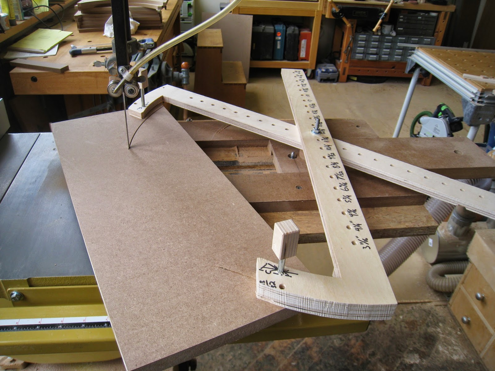
Auto-regulator: Circular logic, Part I
The top of the Auto-Regulator is curved, and tapers in thickness. Most of the methods I've seen for cutting a radius involve driving a screw through the center, and using that as a pivot point. And that works well enough for many things. But in this case, I'm working not only with two different radii, but with two different centers. And that starts to get sticky.
Because of all of the curves I have to cut into the blank, I need to start with 12/4 stock. The end result will be an arch with a 7.5" inner radius, and an outer radius of 11.5". Using the screw through the center technique, I'd want some extra material to contain said center hole. To use the simple, drill a screw into it method of curve cutting, I'd need to drill a center hole through a 12/4 beam that would have to be at least 12-13" wide enough to also contain the center. The finished part would be 15" long, and could be contained within a 7" wide board. There's enough waste involved in cutting an arch, without adding 6" of width to a 15" long blank of 12/4 walnut, just for the sake of locating the center. 13" wide 12/4 walnut isn't exactly rare, but it's not exactly lying around, either. And it's certainly not cheap.
A side note: Not only would the above method be incredibly wasteful, but a 6" x 15" blank would also fit squarely into that sweet spot on the Venn diagram of 'I can't throw this out, it's too big,' and 'I'll probably never actually use this.' And that's a recipe for hoarding scraps.
Added to that, I had this hair-brained idea of making a rough cut on the band saw, and then moving directly to the router table with the same jig, for a finish pass.
And so it was that I set out to untangle radiused cuts (inside and outside radii) on pieces that aren't wide enough to contain the pivot point... and a few other things.
---
Most of the radius cutting that Ive seen involves driving a screw through the geometrical center, into a precisely placed hole on the jig that's the proper distance from the cutting action. But the screws are usually short, it's almost impossible sometimes to see where you're supposed to be driving it into... and it never really felt like an accurate method. Not only that, it doesn't allow for subsequent fine tuning: I can always take 1/16" off of a straight part on the table saw. But I can't do that with the wood screw technique for curve cutting. Especially not if the relevant dimension is the concave side of the cut, because the process involves cutting away the center of the curve. In that case, you just have to make a new blank, and cut a new piece.
So I simplified things. Or, it could be argued, made them more complicated, to make them more simple.
The base mounts to the band saw table. And on top of that is a sliding dovetailed piece, to adjust for different radii, with two options for pivot centers: a removable pin that sticks up, to be used with a 1/4" hole, and a 1/4" brass shelf pin sleeve that serves as a bushing for a center that will be seen shortly. The pin started out as a 1/4-20 bolt that was only partially threaded. I cut it off, chucked it up in a hand drill, and domed the end with a bench grinder.

Making the cut on the band saw is as simple as I assumed it would be.

As I said, I also wanted to be able to make finishing passes on the router table. The jig below is a sliding mount for two more centers, as on the band saw. The idea is that I should be able to set up whatever jig I'm going to use, and move directly from the band saw to the router table.

Part of the problem I had with cutting an inside radius with the traditional screw-center method is that you only get one shot. After that, if the radius isn't quite big enough, you no longer have a center to work from, because you've just removed the concave part, from the center that was your reference point. I came up with the idea of a scissoring pair of arms to mount to a blank, and the only problem I had then, was that I'd cut right through the arms when I used it. So, I came up with this:

Again, 1/4" bolts cut off into pins. The pins slide through the jig, into 1/4" holes that are laid out and precisely drilled in the blank. The dog-leg shape is there to give clearance for the blade to exit the material without cutting into the arms of the jig. And, the pin being used for the pivot point slides into the brass bushing in the band saw jig, or the router table jig.So the whole pivoting assembly can be simply lifted off of the band saw table, and dropped onto the router table for a finish pass.

Coming up: laying out the mounting holes, using the jig to make a bending form, and a few other things...
To be continued.
Wednesday, March 26, 2014
BFFI to the rescue

Accuracy is still an issue. I have a long-term solution, but it hasn't been implemented yet. And, to borrow an unfortunate, albeit accurate quote, "You don't go to war with the army you want. You go with the army you have."
Bombs away...
Apropos, then, that I borrow from that great military tradition of Brute Force and Ignorance. If at first you don't succeed, get a bigger hammer. Above, I'm using a 3 lb hammer and a center punch to make the Kreg miter bar fit my miter slot in an ugly, if workable way.
Tuesday, March 25, 2014
Oldie but goodie shop tip: cheapo glue bottle

Glue bottles at the fancy store will run $2-3 at the minimum. You could go the restaurant supply route and pay the same for a refillable ketchup bottle. And in either case, they'll still clog up, need to be cleaned out with a drywall screw, and not last too long.
This one will only cost you a nickel, it comes with a drink of your choice, and for some chemical reason that's beyond my pay grade, the glue doesn't stick too well to the top. When it dries, it pops off pretty easily.
No, it doesn't have a roller, and it won't get into crevices, but that's what glue brushes and scraps are for.
(S)Crap! Another use for scraps! I'll put that in the next roundup...
Monday, March 17, 2014
MFT: quick tip, checking miter angles before cutting

I'm set up to make a mitered cut at a particular angle, that's not a simple 45 degree angle. The board being cut will be used for a shooting board, so having an accurate cut is important.
I could try to check the angle at the guide rail, but there's not a lot of length to register the gauge, and because the edge of the rail is higher than the edge of the board, I can't solidly register against both at the same time.
Because the rail is calibrated to be parallel/ square to the holes in the top, and the holes are all CNC cut at the factory, I can actually check the angle from anywhere on the table, using Qwas dogs and a sliding bevel gauge: The angle is the same in the middle of the table as it is at the edge of the guide rail. Additionally, I get a longer hunk of board to reference from on this side of the guide rail. That extra length generally spells better accuracy, provided the board is straight. And, having the bevel gauge on a solid surface, rather than out in thin air helps to hold the gauge steady and ensure a good read during the procedure.
In this picture, I'm using a 10" Shinwa bevel gauge. I love these things.
Tuesday, March 4, 2014
Japanese chisels and plywood bits?

This was a 'duh' moment for me yesterday.
I like having paired tools... Chisels that mate with router bits and so on. It helps to have the right size chisel to square up the end of a groove.
Alas, So-called 'Plywood bits' are all under-sized, to match the thickness of plywood, which is similarly under-sized. So a 1/4" chisel won't fit into a groove for 1/4" plywood, for instance, by a mere 1/64". Then I remembered that the real issue is that the plywood isn't actually made to SAE dimensions: It's metric, and sold here in the US as nominal 1/4" (15/64", or 6mm) nominal 1/2", (31/64, or 12mm), and nominal 3/4", (23/32, or 18mm).
Oh, wait. I do have those sizes. Most of my Japanese chisels are metric. Sweet! I now have router bits that pair with those chisels.
(Actually, I've had the bits for 7 years, and the chisels for 9, but only realized the correlation yesterday.)
Obviously, nobody should tell this to Wilbur Pan. He gets enough ribbing about Japanese tools and hardwoods... Japanese tools and plywoods might just be too much for him.
Saturday, March 1, 2014
It IS, or it Isn't.
Any time I want to start doing better work, I discover, again, that I need to get back to basics. Every time I come back to it, everything boils down to a very simple question: Is it, or isn't it? Is it square, or isn't it? Is it straight, or isn't it? Is it a properly fitting joint, or isn't it? In an age of marketing hype, internet commentary, and the ongoing pursuit of hyperbole, this just isn't sexy. But it was never meant to be. When it comes down to it, either something works, or it doesn't.
It doesn't matter if I spend $93 on a Starrett combination square, or $300 on a try square from Bridge City Toolworks. 90 degrees is 90 degrees. This isn't an amplifier that goes to 11. There's no way to make it louder, or pretend that straight and square can be in any way cranked up, because attitude and ego have no impact whatsoever on the pure physical reality. Fancy colored aluminum and T-track and other trendy, photogenic enhancements have no effect on geometry.
It Is, or It Isn't.
---
I've been fighting a pitched battle with my cross-cutting miter head for years now. I remember reading Chris Schwarz saying that he really, really wanted a dedicated 90 degree miter head. And I remember thinking that this was a no-brainer, because 'Straight' and 'Square' are the two first things you need to establish reference surfaces to do just about anything. The problem is, it seems like most of the miter heads available for sale by the usual suspects have sacrificed accuracy and/or reliability, for adjustability, and ease of re-calibration. In other words, you can make it square, you just can't make it stay square. In the end, I noticed in one of his shop photos that the Schwarz finally settled on a $600 Jessem sliding table for his table saw. (No idea if he kept it when he bought his new saw.)
These are a couple of $60 miter heads from Incra. (Please forgive the fuzzy photo) I bought them because the steel construction, and caveman simplicity of the notched angle settings seemed like it would be pretty bomb proof. The issue I discovered is that the fence bracket... the bent, vertical surface that the miter fence will bolt to... isn't so solidly attached. It's bolted on, with 4 screws. They're basically 1/8" screws, through 1/4" holes, and there's so much slop involved that you can be pretty sure on any given day that they're not going to be square. You can easily knock them straight again, I guess, but I'd rather have something I can rely on.

The one on the left was my first real attempt in trying to get something workable out of this setup. About a year ago I took those 4 mounting screws out, and drilled and tapped the holes in the steel plate for 1/4-20 bolts, figuring 1/4" bolts should fill the 1/4" holes just fine. They don't, 1/4-20 bolts start out as 1/4" stock, and after the threads are cut, aren't quite 1/4". But they were better, anyway. They bolted down well enough, I cut and ground the bolts to be flush with the underside, and then I clamped the head rigidly at 90 degrees, and drilled and tapped two holes that go directly down into the bar, to fix it at 90 degrees. Now, like I said, the stability of this whole thing really relies on those 4 bolts. (And the fit of the miter bar, but we'll get there in a minute.) And because the 1/4" bolts don't quite fill those 1/4" holes, things again went off-track.
Many an F-bomb has been dropped on this miter gauge battlefield.
The arsenal has actually expanded to include the venerable MF-bomb, the GD-MF-WTF-bomb, and the always fearsome, angry silent gripping of the edge of the table.
And, as always, such violence never really solves the problem.
The other day, I checked for square, and sure enough, it wasn't. Again. So, I set it to square, and drilled and tapped through the head and the fence bracket, for 4 set screws, to hold the alignment as well as I could get it to, short of welding it. (Fire in a wood shop is bad, and thin steel doesn't always weld very well, or at least not without warping.)

Next step was to tackle the bar. Like the aluminum Kreg miter bar, these steel bars are undersize by 1/64"-1/32" or so. The expanding plastic washers are junk. They're soft, and they give the illusion that they'll fix the problem. But they'll wear quickly, need to be recalibrated, and so in the meantime, the gauge can't be trusted.
So, I drilled and tapped the bar like I did the other day to a Kreg bar.

And I took the screws that go through the plastic doo-hickeys, and used them in those holes. I adjusted until they fit the miter track perfectly. It's an imperfect solution, the steel in the screws is harder than the cast iron, and individual points will cause more wear than a perfectly fitted steel bar, but for now, they'll do.
I re-mounted the fence to the miter head. It was very close to being perfectly square along 18" of miter fence. Given all of the hack-shop jerry-rigging that's been going on here, it's only natural that a little bit of error crept in somewhere. I'm not happy about it, but I fixed the alignment of the fence with 2 layers of tape. I'm relatively happy with it, as long as I can trust the miter head. Which I don't, really. When something I want to trust lets me down as many times as these miter heads have, it's hard to patch that relationship, even with drilling and tapping and adding of more screws, and so on. But for now, I'll invest a little faith that my set screw idea has actually, you know, done something.

When I went to try it out, the bar jammed in the track. My adustments were too good: If the bar's even slightly out of square to the track, it binds. So I loosened the fence, let the miter head and bar settle into their desired position, and re-tightened the fence. NOW, it works. The plywood in the picture is square, along a 10" cut, which is the widest stock I can cut with a miter head on this saw. Bigger cuts require a sled. And a sled will also require making accurate bars... and I don't have the heart for that right now.
Maybe next week.
--- Side Note---
I bought the Kreg miter gauge after realizing that the Incra was as bad as it is, because the head that bolts to the bar on the Kreg setup is one piece, unlike the Incra. So I won't have to worry about a loose fence bracket. The miter bar is long, but it's aluminum, undersized, and has a lot of plastic set screws to make up the difference. They're problematic, because just going in and out of the slot wears on them a lot, and I can never really trust that the calibration is good.
In the end, it doesn't matter how much money you spend on the head, if the bar isn't good. If the bar is sloppy, the miter gauge will be accordingly sloppy... or the crosscut sled, miter sled, or any other accessory you mount to that bar. As I've said before, any decent jig needs a way to align the material, a way to control the material, and a way to accurately guide the material past whatever's doing the cutting. An accurate bar is required to get accurate results.
The head on the miter gauge may be one piece, and Kreg's L-shaped fence profile and production stops are great. You can even buy a 4' chunk of it, to make a really long miter gauge fence. (I did.) But in the end, none of the anodized aluminum sexiness matters. I still can't trust the bar to be accurate. There is no miter gauge that goes to 11: Square is square, accurate is accurate, It IS, or It Isn't.
And it isn't... Or at least, not reliably so.
---Epilogue---
I share shop space with Mark DelGuidice, among others. Mark loves his General table saw. He loves it enough that he bought an even bigger one for the shared machine room. The big one has 1" miter slots, as opposed to the 3/4" slots that most machines have. The miter heads are very heavily cast, with machined steel bars that are T-shaped in cross-section, and they fit those slots PERFECTLY. No alignment screws, no slop, no apologies. They were made well, and made right, and they fit like they should.
I walked back into his own personal space, and took a look at the head for his 10" saw. The head is heavily cast, and the 3/4" steel bar isn't T-shaped, but it fits the slot PERFECTLY. No alignment screws, no slop, no apologies.
So, long-term, I think I'm going to have to look into getting a real miter gauge, with a real steel miter bar, one that fits like it should. And if I can't find one, I'll have to make one... Or have one made. I'm tired of fighting losing battles with half-hearted aftermarket parts to get them to work like they should. I'd love to get a dedicated 90 miter head that's solid and reliable enough to try something like William Ng's 5-cut to square method.
But at this point, if I have to go through all of the above to work with the Stupid, Flaming, God-Forsaken POS that I have, it's not worth it.
(Bombs away... I'm off to to throw things now.)
---Second Epilogue---
I talked to Mark about this later on. His recommendation was to buy cold-rolled steel bar stock. It's typically 2-3 thousandths under-size, but it's a very close fit, which can be fine-tuned using the center-punch method if you still require added accuracy. He showed me a few light dimples on his regular miter gauge, and sure enough, there are some barely perceptible dimples where he tapped it, in situ, with a nail, to fit the slot perfectly.
Another advantage of steel is that it glides much better than aluminum, which has a tendency to stick.
And, a chunk of cold rolled steel from McMaster is MUCH cheaper than a porrly-made, massively over-wrought, woefully undersized jig bar from Woodcraft or Rockler. Sure, you have to drill your own mounting points, but that's a very, very simple operation, compared to the saga described above.
It doesn't matter if I spend $93 on a Starrett combination square, or $300 on a try square from Bridge City Toolworks. 90 degrees is 90 degrees. This isn't an amplifier that goes to 11. There's no way to make it louder, or pretend that straight and square can be in any way cranked up, because attitude and ego have no impact whatsoever on the pure physical reality. Fancy colored aluminum and T-track and other trendy, photogenic enhancements have no effect on geometry.
It Is, or It Isn't.
---
I've been fighting a pitched battle with my cross-cutting miter head for years now. I remember reading Chris Schwarz saying that he really, really wanted a dedicated 90 degree miter head. And I remember thinking that this was a no-brainer, because 'Straight' and 'Square' are the two first things you need to establish reference surfaces to do just about anything. The problem is, it seems like most of the miter heads available for sale by the usual suspects have sacrificed accuracy and/or reliability, for adjustability, and ease of re-calibration. In other words, you can make it square, you just can't make it stay square. In the end, I noticed in one of his shop photos that the Schwarz finally settled on a $600 Jessem sliding table for his table saw. (No idea if he kept it when he bought his new saw.)
These are a couple of $60 miter heads from Incra. (Please forgive the fuzzy photo) I bought them because the steel construction, and caveman simplicity of the notched angle settings seemed like it would be pretty bomb proof. The issue I discovered is that the fence bracket... the bent, vertical surface that the miter fence will bolt to... isn't so solidly attached. It's bolted on, with 4 screws. They're basically 1/8" screws, through 1/4" holes, and there's so much slop involved that you can be pretty sure on any given day that they're not going to be square. You can easily knock them straight again, I guess, but I'd rather have something I can rely on.
The one on the left was my first real attempt in trying to get something workable out of this setup. About a year ago I took those 4 mounting screws out, and drilled and tapped the holes in the steel plate for 1/4-20 bolts, figuring 1/4" bolts should fill the 1/4" holes just fine. They don't, 1/4-20 bolts start out as 1/4" stock, and after the threads are cut, aren't quite 1/4". But they were better, anyway. They bolted down well enough, I cut and ground the bolts to be flush with the underside, and then I clamped the head rigidly at 90 degrees, and drilled and tapped two holes that go directly down into the bar, to fix it at 90 degrees. Now, like I said, the stability of this whole thing really relies on those 4 bolts. (And the fit of the miter bar, but we'll get there in a minute.) And because the 1/4" bolts don't quite fill those 1/4" holes, things again went off-track.
Many an F-bomb has been dropped on this miter gauge battlefield.
The arsenal has actually expanded to include the venerable MF-bomb, the GD-MF-WTF-bomb, and the always fearsome, angry silent gripping of the edge of the table.
And, as always, such violence never really solves the problem.
The other day, I checked for square, and sure enough, it wasn't. Again. So, I set it to square, and drilled and tapped through the head and the fence bracket, for 4 set screws, to hold the alignment as well as I could get it to, short of welding it. (Fire in a wood shop is bad, and thin steel doesn't always weld very well, or at least not without warping.)
Next step was to tackle the bar. Like the aluminum Kreg miter bar, these steel bars are undersize by 1/64"-1/32" or so. The expanding plastic washers are junk. They're soft, and they give the illusion that they'll fix the problem. But they'll wear quickly, need to be recalibrated, and so in the meantime, the gauge can't be trusted.
So, I drilled and tapped the bar like I did the other day to a Kreg bar.
And I took the screws that go through the plastic doo-hickeys, and used them in those holes. I adjusted until they fit the miter track perfectly. It's an imperfect solution, the steel in the screws is harder than the cast iron, and individual points will cause more wear than a perfectly fitted steel bar, but for now, they'll do.
I re-mounted the fence to the miter head. It was very close to being perfectly square along 18" of miter fence. Given all of the hack-shop jerry-rigging that's been going on here, it's only natural that a little bit of error crept in somewhere. I'm not happy about it, but I fixed the alignment of the fence with 2 layers of tape. I'm relatively happy with it, as long as I can trust the miter head. Which I don't, really. When something I want to trust lets me down as many times as these miter heads have, it's hard to patch that relationship, even with drilling and tapping and adding of more screws, and so on. But for now, I'll invest a little faith that my set screw idea has actually, you know, done something.
When I went to try it out, the bar jammed in the track. My adustments were too good: If the bar's even slightly out of square to the track, it binds. So I loosened the fence, let the miter head and bar settle into their desired position, and re-tightened the fence. NOW, it works. The plywood in the picture is square, along a 10" cut, which is the widest stock I can cut with a miter head on this saw. Bigger cuts require a sled. And a sled will also require making accurate bars... and I don't have the heart for that right now.
Maybe next week.
--- Side Note---
I bought the Kreg miter gauge after realizing that the Incra was as bad as it is, because the head that bolts to the bar on the Kreg setup is one piece, unlike the Incra. So I won't have to worry about a loose fence bracket. The miter bar is long, but it's aluminum, undersized, and has a lot of plastic set screws to make up the difference. They're problematic, because just going in and out of the slot wears on them a lot, and I can never really trust that the calibration is good.
In the end, it doesn't matter how much money you spend on the head, if the bar isn't good. If the bar is sloppy, the miter gauge will be accordingly sloppy... or the crosscut sled, miter sled, or any other accessory you mount to that bar. As I've said before, any decent jig needs a way to align the material, a way to control the material, and a way to accurately guide the material past whatever's doing the cutting. An accurate bar is required to get accurate results.
The head on the miter gauge may be one piece, and Kreg's L-shaped fence profile and production stops are great. You can even buy a 4' chunk of it, to make a really long miter gauge fence. (I did.) But in the end, none of the anodized aluminum sexiness matters. I still can't trust the bar to be accurate. There is no miter gauge that goes to 11: Square is square, accurate is accurate, It IS, or It Isn't.
And it isn't... Or at least, not reliably so.
---Epilogue---
I share shop space with Mark DelGuidice, among others. Mark loves his General table saw. He loves it enough that he bought an even bigger one for the shared machine room. The big one has 1" miter slots, as opposed to the 3/4" slots that most machines have. The miter heads are very heavily cast, with machined steel bars that are T-shaped in cross-section, and they fit those slots PERFECTLY. No alignment screws, no slop, no apologies. They were made well, and made right, and they fit like they should.
I walked back into his own personal space, and took a look at the head for his 10" saw. The head is heavily cast, and the 3/4" steel bar isn't T-shaped, but it fits the slot PERFECTLY. No alignment screws, no slop, no apologies.
So, long-term, I think I'm going to have to look into getting a real miter gauge, with a real steel miter bar, one that fits like it should. And if I can't find one, I'll have to make one... Or have one made. I'm tired of fighting losing battles with half-hearted aftermarket parts to get them to work like they should. I'd love to get a dedicated 90 miter head that's solid and reliable enough to try something like William Ng's 5-cut to square method.
But at this point, if I have to go through all of the above to work with the Stupid, Flaming, God-Forsaken POS that I have, it's not worth it.
(Bombs away... I'm off to to throw things now.)
---Second Epilogue---
I talked to Mark about this later on. His recommendation was to buy cold-rolled steel bar stock. It's typically 2-3 thousandths under-size, but it's a very close fit, which can be fine-tuned using the center-punch method if you still require added accuracy. He showed me a few light dimples on his regular miter gauge, and sure enough, there are some barely perceptible dimples where he tapped it, in situ, with a nail, to fit the slot perfectly.
Another advantage of steel is that it glides much better than aluminum, which has a tendency to stick.
And, a chunk of cold rolled steel from McMaster is MUCH cheaper than a porrly-made, massively over-wrought, woefully undersized jig bar from Woodcraft or Rockler. Sure, you have to drill your own mounting points, but that's a very, very simple operation, compared to the saga described above.
Tuesday, February 25, 2014
Working out a better miter bar... V.1

I've said before that jigs need three things: A good way to position the stock in alignment, a good way to hold it in alignment, and an accurate way to guide the stock past the cutter.
I've been generally frustrated with store bought miter bars for use in jigs. They suck. Period. And the reason that's such a problem is that they're the foundation for any jig you'll make. Any effort you put into making accurate fences, or solid work holding, will be undermined by the fact that you can't move the jig past the cutter in a way that's accurate enough.
There's a basic problem that manufacturers have: they don't know the exact width of YOUR miter slot. Most are 3/4". But that's ballpark, and subject to error. The only solution accessory manufacturers have is, make sure your error margin is greater. So, stock bars, like the one in the photo, are generally shy by a full 1/64". Longer bars will theoretically reduce the slop in the angle, but they still aren't great. And the goofy plastic shimming measures all share a common problem: They're plastic, and subject to wear from use, or damage from day to day bounces in and out of a machined cast iron surface. The end result is that there's a decent chance that, even with a ridiculously accurate miter gauge or sled, when the stars (and plastic afterthoughts) aren't in rare alignment, your joints will have gaps that don't need to be there.
This is a chunk of Kreg bar, drilled, tapped, and countersunk for steel screws. The tap I used was chosen because it's worn, so the threads are a little snug. That way they'll hold an adjustment better. There's zero slop in the miter track, now that it's properly adjusted. It's not my ideal solution, but it's miles ahead of what I had to work with before.
Sunday, February 23, 2014
Shooting board for truing long miter joints
Project X requires long miter joints to make up vertical members. The longest is 52" long. And that's a lot of room for error. So, I built this shooting board to true the joints before gluing up.
Setting up... In this picture, there are small offcuts to the right of the part to be trimmed. Those are there to balance out the board that will be clamped on top to guide the plane. There's also an end stop.

With the upper guide board on top... The board needs to be aligned with the lower track before being clamped into place. Being me, I tried to think up a way that would do this more automatically and precisely, but this was the simplest and most practical way to move forwards.

Trimming the beveled edge. With a properly set chip breaker, grain direction isn't really much of an issue. Popular Woodworking will be running an article in their April issue on how to do that.
Shop tip: The finished surface will come to a delicate edge. Laying the boards flat on the bench, or out of the way on an accessory table, with this edge down, will help keep them from getting damaged. And, don't do this until the step just before glue up, so you don't have to worry about moving them around the shop. The less you have to handle wood with a sharp 45 degree edge, the less you'll expose it to getting beaten up.

The finished joint... is as close to perfect as I can get. (Picture of the dry fit)

Setting up... In this picture, there are small offcuts to the right of the part to be trimmed. Those are there to balance out the board that will be clamped on top to guide the plane. There's also an end stop.
With the upper guide board on top... The board needs to be aligned with the lower track before being clamped into place. Being me, I tried to think up a way that would do this more automatically and precisely, but this was the simplest and most practical way to move forwards.
Trimming the beveled edge. With a properly set chip breaker, grain direction isn't really much of an issue. Popular Woodworking will be running an article in their April issue on how to do that.

Shop tip: The finished surface will come to a delicate edge. Laying the boards flat on the bench, or out of the way on an accessory table, with this edge down, will help keep them from getting damaged. And, don't do this until the step just before glue up, so you don't have to worry about moving them around the shop. The less you have to handle wood with a sharp 45 degree edge, the less you'll expose it to getting beaten up.
The finished joint... is as close to perfect as I can get. (Picture of the dry fit)
Wednesday, February 19, 2014
80-20 to the rescue, again.

I'm about to do a lamination where 2 pieces will be laminated around a third, sharing a mitered edge. Problem is, the wood is very, very slightly bowed. The lamination will fix that, but getting a clean beveled edge on bowed stock with the table saw is... Dicey, at best. So, each beveled edge will be rough cut, and then I'll use a long shooting board to true the bevels. But, that requires that the shooting board has a reference-straight edge to start with. For whatever reason, this particular piece of plywood is out of straight by a bit. So, I'm using a chunk of 80/20 extrusion to pattern-rout a straight edge.
That's one thing I love about these extrusions. They're not technically machinist-straight-edge-reference straight... But they're close enough for woodworking. And this 7' piece was much cheaper than a certified straight edge of similar length. Great for, say, checking an 8' bench surface when you're flattening.
AND, it's straight enough to use as a pattern, for trimming a reference edge on a jig. But, Please note the tape on the bearing: The edges on the router bit are almost, but not quite, in line with the diameter of the bearing. So I added tape until I was comfortable that the bit wouldn't touch my aluminum straight edge.

Subscribe to:
Posts (Atom)