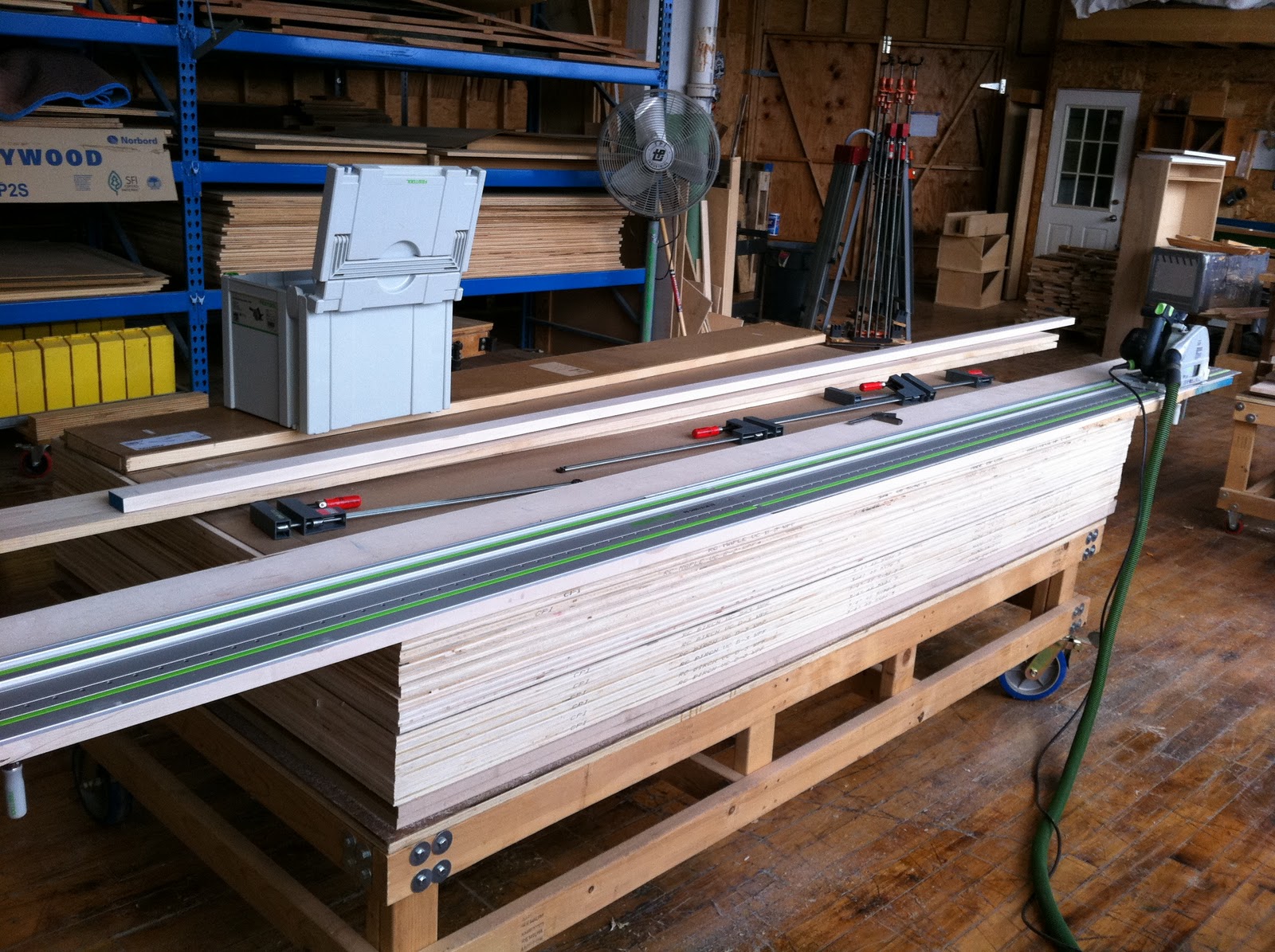
Showing posts with label Vises. Show all posts

Tuesday, December 3, 2013

Using the French chair maker's vise on the hayrake table.


Using 80-20 for most of my jigs saved me a lot of time, but I still needed a fast way to cut shoulders on the 45 degree tenons. Given that it was only one table, it didn't make sense to me to spend a lot of time engineering a way to treat it like a production run. So, I used the French chair maker's vise that I built back in July of 2012:


It's really simple to use. The top surface is reference-flat. The material is clamped lightly in the vise, and the shoulder line is lined up with a gauge stick that's set to the height of the saw blade in a side-cutting saw that's also part of this arrangement. Once everything's in alignment, the material is clamped, and the saw cuts both shoulders to be in exactly the same plane. Clever, simple, efficient. Gotta love that...


 SO how accurately does it cut? Very accurately, as long as the gauge stick is right on, which is the current problem. As pretty as this picture is, I actually need to make a new gauge stick. The tenon sticks up above the vise, I'm actually cutting on the wrong side of the line. The joints all came together fine, but the tool should be working more accurately than this. (To be fair, the blade was pulled out farther than normal for these shoulders, so there may be some error introduced there, but even still... I need to give this some attention.)


Clean shoulders will make or break the look of a mortise and tenon joint, so they have to be done right. For this particular table, this was the most efficient way to get the job done that I could think of. For multiple tables, I might set up something on the table saw (if it was set up, which it's not, yet) or with router templates. But for one table, (8 angled joints) the chair maker's vise is such a quick and intuitive tool that it just made all the sense in the world to cut the shoulders that way.

Joinery's done... chamfers are next. 

Wednesday, July 25, 2012

The basic premise...

So, this is the gizmo I've been working on. It's in a mostly-done state right now, still needing to be burnished and waxed.

What you're looking at is a stoutly made, fully enclosed vise, made with a veneer press screw. The entire top surface is reference-flat, and at 90 degrees to the inside surfaces of the vise. The purpose of this device is to assist in cutting co-planar tenon shoulders, regardless of the angle that's required. The basic theory is this: clamp the part to be cut into the vise, and align the shoulder scribe lines with the top edge of the gauge stick. The saw will then be used to cut the shoulder, sliding back and forth across the top surface of the vise. This will ensure that all shoulder surfaces are 100% in the same plane. In the photo above, the part being cut is at a simple angle. I will also make a pair of pivoting pads, so that parts may be set up for compound angles.

Why did I bother with this?

The tenon shoulder is the most critical, visible part of a mortise and tenon joint. If one of them is poorly cut, there will be a gap, or the specified dimension will be changed. On a table stretcher, for example, the distance between legs is defined by the distance between tenon shoulders. If you're just bracing table legs, maybe this isn't such a big deal. But if you're making another part that will form a drawer enclosure, that dimension is more critical. If you're making a dresser, and you have many such parts, you really want them all to be the same. When you're fitting the joint, mortise walls can be pared back, tenons can be trimmed and shimmed, but cutting the shoulder is a one-shot operation. It has to be done right the first time.

Cutting square tenon shoulders is a snap with a table saw, and it's not much harder with a hand saw. Cutting simple angled tenon shoulders is pretty easy, too, though grain direction on porous wood can throw the saw off track if you're not careful.

Cutting tenon shoulders at a compound angle is possible on a table saw, but it's a hassle, and it took some interesting jiggery to make it work when I was learning to make chippendale style chairs in school. Cutting a compound angle joint with a hand saw is probably easier with a hand saw in that regard, but even still, there's a lot of care required. I suppose in a production environment, and given reference faces, I should just use a Domino machine and have done with it. But in a home shop environment, how do you set up for compound angle joinery and make it easy? Well, the gizmo at the top of this post is the answer.

This isn't my design. This is something that was shown to me when I was in school, that was brought over by a french chair maker. There's a companion jig that provides a way to clamp a piece and plane a reference flat surface, which will then be mortised into.  That'll possibly come next, but for now, this seemed like it would provide more capability.

Thursday, May 19, 2011

Sjobergs hold down

One of my problems with my bench is that, like many other benches from Sjobergs, it has a skirt, which makes it had to clamp things down to the surface. It's a wide-ish skirt, so I can clamp close to the edge of the bench. But past 3 inches or so, there's a hollow, so my regular F-clamps don't register properly. I thought about flipping the bench over, and simply gluing in a few strips of extra wood. But that means either flipping it with the Emmert still attached, which is heavy, or taking the Emmert off, and it's heavy. And then there's the need to re-drill all of the dog holes, and hoping like hell that the new lamination doesn't cause the top to start warping again. That's the last thing I need... so far, it's been behaving itself. So I broke down the other day and bought the hold-fast that Sjobergs makes for the Elite bench.

I would rather buy a holdfast from Veritas... or from Gramercy, even. I have a couple of Gramercy hold fasts at home, they're great. But the bench has 1" holes, instead of the 3/4" that everyone else seems to like to use.  I suppose I could find someone to custom forge me a set of serious, old-school holdfasts... but that takes much more time and planning than an impulse buy.

The Sjobergs hold down is pretty stout, and the just-under 1" rod is actually solid steel, instead of a plastic filled pipe, like the smaller version they make for their smaller benches. It's pretty clear that the whole unit is designed to be bolted through a thinner surface, hence the flange, and the threads on the bottom. (Though the nut for doing so isn't included, which seems weird to me.) In that context, it makes sense to have the arm slide up and down. But since I'm dropping the thing into a hole in the benchtop, it seems a bit redundant. It works fine, it's just quirky and weird. In the end, it works fine, so whatever.

Either way, it works, which is, I guess, all that's required. I do wish they had used a nice grippy wooden handle, instead of a plastic one, which isn't so grippy. What's the use having such a stout clamp if you can't grip the handle hard enough to really get down on it?

So, as a tool, it works as should be expected. But the design is somehow less than I expected... which is fitting, I guess, since the bench started out the same way.

Sunday, May 15, 2011

Evolving techniques with the Domino

So, I apologize for neglecting this thing. It's been a busy spring, and I've been blessed with some really enjoyable work. The downside is that I've been busy as hell, and haven't really had the time to spend blogging about it.

Here are a few of the highlights of some of the process improvements that I've been working on. 

---Improved Domino technique---

Ron Wenner's Domino plate is great. And it was very useful to clamp the plate directly to the work I was doing. But I found that I had to turn the machine off after every mortise to adjust the clamp. So I drilled and tapped holes for a chunk of T-track to use as a third hand, to hold one end of the clamp in place while I tightened it.

That really helped with clamping more easily, but it revealed one fundamental problem: The marks on the bottom of the tool weren't properly aligned with the actual center of the mortise. Every joint I made was slightly mis-aligned by more than 1/16". I was less than pleased.

The only solution I could come up with, after much head scratching, was to erase and lay out new alignment marks. So I made a test piece to show the discrepancy, and I got out some WD-40, some wet-dry sandpaper, and erased the old marks. I used the test piece to lay out the new lines, and scribed them in pretty deeply. At this point, any discrepancies I have are the result of sloppiness in laying out my markings, which means my errors are now in the 1/64" range, which is much better.


---On using the Emmert---

I can't say enough about the Emmert vise. It's been great for all of the regular things, but the ability to go Horizontal has been huge in conjunction with the Domino.

Thursday, January 20, 2011

Shop tips 1/20/11

This is the first entry of what will hopefully become an ongoing, but probably not regular segment on things I find that help with productivity.

Reliably repeatable crosscutting of long parts.
I was trying to find a way to cut long parts for some frame and panel sub-assemblies the other day. I have a long fence that hooks onto a miter gauge, but the parts were even longer than that. The solution that I came up with was to use the long bar to the right of the blade, and set the length of the part with the table saw fence. Since this is an inherently dangerous operation, I needed a way to use the fence to set the length, and then have the fence slide out of the way. But I had 8 of those parts to cut, and only felt comfortable cutting one at a time. And I wanted a precise way to position the fence.

I have a length of T-track set into the extension table, which I put in there to hold fence settings, in the event that I needed to cut something smaller, and then go back to the other setting. I switched that up a bit, using the setting holder as a stop for bringing the fence back the same position again and again.


Another use for the pattern vise
I've been seriously loving the Emmert vise. Oh, man, so worth having.

I was using my Festool domino to join the frame and panel assemblies together yesterday. I'm used to clamping every piece to the bench top, and un-clamping every time the part needed to be moved or flipped... sometimes having to use 2 or 3 clamps on the longer boards. Then I remembered that the Emmert pivots 90 degrees. I feel like a tool glutton. I'm in hog heaven. Using the vise is SO much easier than using clamps.


Accurately edge jointing really long boards
I'm not sure if this is really a helpful post, or if it's just me showing off some of my coolest toys tools.

In any event, this was the easiest method to straighten a 12' long board that I've ever used. I love Festool.

Sunday, October 24, 2010

Finished installation, and Final thoughts on mounting an Emmert


Edit: 12/19/2011: I have written up a more concise and better illustrated narrative on how to install the Emmert Pattern Maker's vise here


As a result of some of the comments I got from the last post, I wanted to show how the final product turned out, and write up a more cohesive and useful narrative for anyone who's planning on installing one of these, or building a bench around one. 

With the vise re-installed, I have a gap of about an inch and a half between the right side of the vise, and the front surface of the bench top. But also notice that the bench top appears to come down a bit at that point. This isn't an illusion, the bench has a skirt under the top that's about 1" thick. The center of the bench is still 3" thick, so it's not as vile a deception as you might think. I think it's mainly so they can flat-pack the bench with the vises installed. The skirt ended here already, to allow clearance for the face vise that came on the bench. I chose to make the cut so far to the right, because it lined up with the cut in the skirt. I think it just looks cleaner. It's a 1 1/2" gap, which is more than necessary, but it's not really a deal-breaker, either.

If I were building a new bench, the top would be full thickness all the way across. I'd laminate all but the last 2", mount the vise, and then get ready to laminate one more piece of wood. I'd also spin the jaws on the installed vise to measure how much clearance I actually needed for the vise to rotate, and cut the last lamination accordingly. On a scratch-built bench, the clearance would probably be under an inch. and then thickness the last piece to be parallel to, and about 1/8" behind the extended plane of the rear jaw of the vise. I know this seems weird. It was in the original instructions for the vise, and it took me a while to figure out why. The jaws rotate. And there's a lot of mass that will be rotating. If you're off a bit, and you go to rotate your work, there's a chance you'll crunch your work into the top edge of your bench. Not cool. If you really need to clamp to the front of the bench, it's very easy to make an L-shaped shim to hang over the front edge, so you can clamp the work to the front of the bench. where the long arm of the L-shape rests on the top surface of the bench.

Another judgment call was the placement of the vise with regard to the left edge of the bench. In this case, I placed the vise to align with the dog holes that I have on the bench as it came from the factory. There's just over 2" of bench sticking out past the left-most edge of the vise. I don't think it's really going to get in the way of my ability to work, but on a new bench, I'd mount the vise all the way at the end, and drill my dog holes to line up with the vise once everything is in.


Notes on installing an Emmert or Emmert clone: 

(edited on 1/27/11 to be more readable)

I assume that anyone who's trying to mount one of these beauties has done at least a little bit of homework first. There's a lot going on here. I also assume you've read enough to know to take most of the vise apart, and work on the install with the least amount of weight possible.

The most visually obvious thing that needs to be laid out is the recess for the plate, and the holes for the three screws. You do NOT want to lay out those screws until the absolute end of the install. There are two more hidden screws that will hold the vise up while you trim and shim to get it aligned and perfect. Once you get it in the way you want it, then you'll know where you need the holes to be, and you can lay out and drill.

I was really, and justifiably, concerned with getting the mount laid out and drilled just right. The placement of those three holes determines the alignment of the vise with regards to the bench, and if they're even a little bit off, everything will be thrown off, even if it's only a little bit. Given the amount of wood that has to come out just to mount the rear jaw, the thought of getting it wrong only after you've done irreparable damage to the bench top is pretty high on the list of things that can persuade someone to steer clear of the greatest vise ever made.

I think it's conceivable to measure and lay everything out so that it will be perfectly installed with no errors. I also believe that weird things happen, iron castings are reliably not 100% square or straight, and that the human mind and hand are both fallible. A bench top is a huge, expensive, ponderous expanse that will display every evidence of your failures if you aren't able to grapple a little bit with the process of mounting your bench vise. No pressure. : ) 

This is usually where I cringe, because as sure as the day is long, I'm gonna slip up somewhere, and I do NOT want to be the yuppie bastard Emmert owner who owns an Emmert vise, but botched the installation, thus proving that I'm unworthy. In the process of hanging this 90 pound monster, I learned the following: Have faith. There's a lot more wiggle room than you think.

In addition to those 3 big mounting screws, which render every error permanent, there are also 2 more mounting screws behind the rear jaw, in a horizontal orientation, which will give you the time to figure things out a bit. Those 2 hidden screws will give you the wiggle room you need to get the install done as accurately as you are hoping to. Do all of the underside excavation first, and rout out the recess for the mounting plate. You may also have to do some hand work to get the fit right... my mounting plate was tapered in thickness from back to front. Once the plate will fit into the recess, mount only the rear jaw, using only those two horizontal screws, and trim and shim until you're happy with the alignment of the rear jaw. You can keep removing the vise while you make adjustments to the notch, until everything is just right. There's room for trial and error. Once you have the rear jaw alignment dialed in, with those two back screws nice and tight, then you can mark out the three holes for the top screws in the mounting plate. Those three screws are just the punctuation mark at the end of the sentence... the finalizing step in the long process of getting it just right. They are not the leap of faith that I was terrified they would be.

I have to point out that accuracy in drilling is important here, because the nature of countersunk screws is to completely mis-align everything if you don't drill the holes just right. But if you've made it this far, you should be just fine...

Tuesday, October 19, 2010

Emmert revisited, and a summation of the process to date.


Edit: 12/19/2011: I have written up a more concise and better illustrated narrative on how to install the Emmert Pattern Maker's vise here

Edit: 11/1/10: The bench is back together, and I've since posted some tips for anyone who wants to install one of these monstrous miracles.

So, I've been playing with... er... USING... the Emmert for a few weeks now, and I've run into a problem. Setting the vise into the front edge of the bench top was simply not a good idea. At least, not the way I was trying to do it. I read Roger Van Maren's account of how to do a flush mount, and it looked nice enough to me. And the lasting impression was that it would be a good idea.

Originally, I had a mental image of a big vise, traced out and neatly inset into the front of the bench. I thought that a reasonable clearance around the vise would be enough to let it rotate freely. It sounded neat, and clean. The reality is that the Emmert Universal vise is Big, Versatile, and it Needs Room to move around. My own mental image of an inset vise has proven to be possible, but impractical, as it restricts the most useful features of the vise.

I struggled with the issues of laying out and mounting the vise, and this is a brief run-down of my experiences in mounting an Emmert U-6 Universal. I'm not saying that this is the way to do it,  I'm simply putting down what I went through to learn what I know now.

The U-6 is huge. The main jaws are 18" wide, and 6" high. This is without the small machining jaws that are on the bottom, which have already proven their worth. The whole thing weighs something in the neighborhood of 90 pounds. This is not like other vises I've installed. Most others I could mount by lying on the floor, holding up with one hand, and drilling and installing mounting bolts with the other. Installing an Emmert is a not so easy.

---------------------------------------------------------------------------------

I knew I wanted the rear jaw to be flush with the bench. But the fact still remained that I needed to figure out a practical way to do an accurate layout, so that I could mount 90 pounds of cast iron with half a hope of getting it where I wanted it.

Eventually I conceived of clamping a board to the front edge of the bench, and wrapping the vise around that. The back face of the board would align the vise with the front face of the bench. Brilliant! After this, I took the vise off, laid down a piece of plywood to trace out my pattern, and put the vise back in place. I used the old pencil and washer trick to trace around the vise, and made a pattern that I could use to cut out my inset. And it worked.


I think that laminating another piece to the front of the bench to be in line with the vise is a better idea than flush mounting. But for those of you who want to keep the front of the bench the way it is, and are cutting into an existing bench top, I think a square cut corner notch is the way to go. But you still need to lay out and align everything before you cut the notch out. And the method I just described proved to be a viable way to do that before you cut into anything.

-Side note on the mounting plate. I mounted the plate to be just below the bench surface, which makes sense to me. But it wasn't a simple routing job. The mounting plate is actually tapered in thickness, and is thicker down where the holes are for the screws. So I had to use a chisel to make the recess deeper at the other end. I had read somewhere that the vise requires #18 wood screws. So, that's what I bought. And when it came time to do the mounting, they turned out to be too big. I drilled out the holes and countersunk further. So, my vise uses #18, but my suspicion is that other vises may call for something smaller. 

-Cutting everything out. Using the pattern I got from tracing out the upside-down vise, I used a router with bearing bits to cut into the bench top. But then I realized that I couldn't rotate the vise within the cutout. So, I broke out the carving tools and went to work. It was a pain in the ass.

AND I had to hog out a trench for the beam that houses the threaded rod. I've seen pictures of the chunk of wood that has to come out to clear the vise hub, but I hadn't really thought about beam clearance. Without the trench, the beam hit the underside of the bench, and the vise wouldn't sit square. Clearly, my bench top is thicker than the ones I've seen other pattern vises mounted to. Or, maybe I am. Or both.

-Recently, I noticed that when the vise is tilted, and I rotated the vise, the top flange of the rear jaw bangs into the top, front edge of the inset. I'd carved out a curved recess to allow the vise to rotate in a vertical direction, but it was looking like I'd have to carve more to allow it to rotate around the top edge of the inset. I decided that I'm not going to keep carving forever to make more and more clearances around the vise. It probably would have been an easy fix, but the process so far has just made things uglier and uglier.


-Flash forward to the other night. I had wrapped up work on another project, and the bench was cleaned off. I took advantage of the opportunity, and took the vise off. I took the bench top to the band saw, and ripped a notch where the vise is to be mounted. I made the crosscut to take the last piece out with a Festool track saw. If there's an irony here, it's that it was easier to move the whole 8' bench top to the band saw to do the ripping, but it was easier to do the crosscutting part with a handheld power tool.


As I said before, if I were going to build a bench to hold an Emmert, I'd laminate most of the top, mount the vise, and then laminate one more board to the front to get the front edge to be flush with the rear jaw. This whole learning process has done nothing but reinforce that opinion.

On the one hand, I hope it'll be the last time I have to deal with any of this, and I can now get back to work. On the other hand, knowing what I know now, it would also be fun, for the sake of the blog, and the people who read it, to do a new install, and document the process a little better. I'm on the fence about writing up my own version of a comprehensive set of mounting instructions; there are a lot of good resources out there already, and between this entry, and the second one, I think I've put up all the information that I would have found to be useful. But if I get enough requests for a step-by-step, comprehensive instruction set, I'll do it.

Monday, September 20, 2010

EMMERT EPILOGUE


Edit: 12/19/2011: I have written up a more concise and better illustrated narrative on how to install the Emmert Pattern Maker's vise here


So, the Emmert is in, it's nice. I haven't used it for much, because I still need to do some carving to help with clearance of the jaws when it's rotating. In short, it rotates just fine when it isn't tilted. Tilting and then rotating, not so good.

I'm debating the virtues of just making a larger, square notch in that corner of the bench top. I feel it will be easier, and look nicer. We'll see...

In other news, I'm working on a refinishing project. nothing fancy, but it'll help pay the bills.

Sunday, September 12, 2010

The Emmert Vise


Edit: 12/19/2011: I have written up a more concise and better illustrated narrative on how to install the Emmert Pattern Maker's vise here

So, now that the top is flat, and the drawers are all re-built, one more major task remained... mounting this vise that I've been sitting on for so long. I got going on this last part of the bench project a few days ago. Once in a while, something clicks, and it all just works out.

There was a lot involved in putting this thing in, because I took the more difficult road. Most of the time, I see these vises mounted in the most simple way possible... which is still pretty involved... but the owners simple mount them to the front edge of the bench without trying to get the rear jaw flush with the face of the bench. I can totally understand why people do it this way: the vise needs a lot of clearance to be able to rotate and tilt and do all of the other things that it does. I'm still knocking down high spots that interfere with rotation at various angles.

Knowing what I know now, if I were to build a new bench that were going to have a pattern maker's vise on it, I think I'd use a hybrid method... glue up most of the bench top, mount the vise to the front edge, and make the last strip of the top thick enough to come up to be in line with the rear jaw once the vise were properly installed. I think it's important to be able to clamp things in the vise and against the front edge of the bench at the same time, which is why I bothered to go through the effort of mounting the vise the way that I did.

There are a few more small things to do to the bench. I'd like it to be an inch or two shorter than it is. And I have a few alignments that I need the make on the vise... the rear jaw is sitting a little bit high. But the grunt work of this detour from daily productivity is pretty much done.

Friday, November 20, 2009

Quick sketch of hard clamping in the Veritas twin screw vise.

So, I mentioned about 2 weeks ago that I would put up pictures to describe what I was talking about, when I said that it was possible to use the vise to really crunch down on something. Rather than re-edit that post, I figured it would make sense to do it this way.

Step one:

Put the object to be held into the left side of the vise. (Or, the side that does NOT have the release pin on the handle.) Both screws will rotate inwards, as shown.

Step two: Pull the release pin. This will allow the handle on the right side to spin freely, while the left side still holds with regular clamping force.


Step three: Rotate the right handle as if to loosen the jaw on that side. Because of the way the vise is built, it will actually lever the right side of the jaw out, a little bit, pivoting around the left hand screw. The force it gets from using the length of the vise as a lever will really crunch down on whatever's being held in the opposite side of the vise.


This isn't always truly necessary, but once in a while you get an oddly shaped object that you have to saw through, or do something else that exerts a lot of force. When it comes to that, there's just no substitute for the application of fundamental physics.

Saturday, November 7, 2009

Veritas Twin Screw Vise... My modifications and supplemental user's manual

Heads up to the reader: This will be one of those technical entries that's up for the sake of posterity, but will be incredibly boring and irrelevant to anyone without this particular piece of equipment. So feel free to skip this one and move on to the other postings, which will talk more about chairs, and shop stuff.

-------------------------------------------------------


This afternoon I was in the shop working on chairs and trying to mount something in the vise. But the problem I've been having with this particular vise is that both screws have been turning independently of each other.

Mechanically, the root cause for this is grub screws that aren't able to bite into the shaft of one of the screws. The left handle is pinned through the end of the screw shaft, but behind that, there's a gear that drives/is driven by a chain. The gear on this side clamps to the shaft using 2 grub screws, oriented at 90 degrees to each other. The chain goes around this gear, linking the left screw to the right screw. The right side has a similar gear, but the gear is hooked directly to the handle by way of a retractable pin. The pin is there to allow the two screws to operate independently, within a small range. All things being equal, this arrangement would work out fine. But, all things are not typically equal, and the issue here is that the retracting pin is a stronger mechanical interface than 2 grub screws. (Thin as that pin happens to be, it's still a better lockup than friction.)

The other root cause of my issues is that I'm simply stronger than the average guy, and I've been known to really crank down on the vise from time to time. The result is typically the same... something's in the vise, and both sides need to be individually tightened... and as a result, the grub screws scrape a little bit around the shaft. Repeat this issue a few times, and there's a small groove around the shaft, requiring that I remove the chain cover, and re-tighten the screws. There's an access window to do this, but it's a dumb idea. My logic is this: The screws should really only be tightened when the vise is actually aligned. And the best way to align the vise is to clamp it shut, tighten both sides equally, and then secure the screws where they are.

Well, eventually I tired of all this nonsense, and simply let both screws turn independently. There are certain advantages to using the vise this way, but the truth is that really, it's just better to use the thing as it's designed to be used.

So, I pulled it apart again today, and fixed the problem once and for all.

Famous last words...? Let's simply say that I have modified the vise to alleviate my issues, and pending further notice, it's working a lot better... but there are specific techniques that bear mentioning.

After removing the cover and aligning the vise per usual, I took one of the grub screws out. Using a transfer punch, I marked the location of the hole on the shaft. I then disassembled everything on the end of the shaft... Handle yoke, gear, and Jaw plate all came off. I then drilled an indentation into the surface of the shaft, to make a socket that the grub screw can mate with, and that will give more purchase to the screw. I put the gear back on, tightened the screw in place, and marked for a second indentation for the second screw. Removed the gear, drilled the shaft, and reassembled everything.

What I should have done in retrospect is used thread lock, too... but I'll do that another time if the gear develops any slop.

What I also should have done is taken better pictures, but it didn't occur to me until afterward that this was worth putting up, so the best I could do was to remove one of the grub screws. You should be able to see the socket I drilled out by looking through the hole where I removed the screw... if you click on the picture above.

In theory, this modification will give the grub screws a mechanical hold, and not just a friction hold, on the shaft. And, in theory, this end will now have a much stronger lock than the small sliding pin on the other handle. The pin is fairly small, and I've heard stories of them breaking... which is probably why a spare pin is included.

So... new vise operating procedures.

Now that the gear for the left screw has such a stronger lock on the shaft, I think it's a safer bet to use that one to tighten the vise with. The risk is that I'll tighten too hard on the right handle, and shear the pin.

So, from now on, I'll do most of the holding work towards the left of the jaw, and tighten with the left handle. The right handle should be able to follow along perfectly well, and it still has the crank handle for quickly running the jaw in and out.

Last technique, one I figured out while running each screw independently... It's possible to exert a lot more gripping force on a board (or anything else) outside of the left hand screw. (As opposed to using the space between the screws) I set up the object to be held, to the left of the left hand screw, and tighten the vise down normally. Then, I thread the right hand screw counterclockwise to move the right side of the jaw outwards. Basically, I'm using the width of the jaw as a long lever, pivoted on the left hand screw. This technique is NOT good for massive movements, and certainly not good for holding tapered work, because the design of this particular vise doesn't really allow for that. But disengaging the sliding pin on the right handle will allow the gear on that side to disengage completely, so the right hand screw can operate independently, and lever the right side of the vise outwards just enough to add a lot more pressure to whatever's being held.

(A more visual explanation is here)

Other modifications:

I made a few small design changes to the way I installed the handles. First, rather than drilling all the way through for the crank handle, I installed a threaded insert in the handle. I just think it looks cleaner. I had to shorten the crank handle bolt accordingly, but that was pretty simple.


Second handle modification. I noticed right away that using the crank handle means locking the handle in place so that it can't roll. There are brass thumbscrews that come threaded into each handle yoke, but I knew right away that these would have issues keeping the handle from spinning if they were only being used on the surface of the wooden handle, with the end result of a scratched up, screwed up looking handle, and an ongoing difficulty in using that crank handle. So, I drilled a hole in the center of each handle, and inserted a brass shelf pin socket. I think they're made by Vertex, or one of the other premium brass hardware suppliers. These sockets have holes drilled in them that are 1/4" in diameter, which fits the brass thmb screws very well. They do a great job of keeping the handles secure, and they keep the crank handle from rotating the right handle around. AND they look a lot nicer than simple holes drilled in the wood, which would most likely wallow out over time.

Friday, October 9, 2009

Vein slapping junkie

So, I've been using the bench I built last year for a while now. It's great, I love it.

But, my recent foray into chairs, and chair shaping has gotten me thinking again. You see, I've been sitting on yet another vise for a while, that I've been wanting to use, but hadn't gotten around to using yet. I've got an Emmert pattern-maker's vise. In essence, these are some of the most versatile vises known to man, and they can swivel in several different directions. In short, they're perfect for weirdly shaped parts, such as those that I'm making now. And I've found myself thinking about it while shaping these parts.

Installing one of these monsters is a trial in and of itself. That's one reason I'd put it off. And they're incredibly heavy, and have been known to warp 2" thick bench tops over time. That's why I haven't wanted to mount it to the bench I have now. I've been thinking about mounting it to the Sjoberg that I've been keeping in the machine room, maybe, and swapping benches after that. But I haven't gone through with that yet.

Then I was bouncing my merry way around the web, and was reminded of yet another vise I'd had my eye on for a while... (http://www.khalafoud.com/media/benchcraftedtailvise.wmv) and had to pull myself out of my reverie. I think it's quite possible that I have a woodworking tool problem.

"Hi, I'm James, and I'm a tool junkie..."