At this point in the series around radius cutting, we have a very reliable way to cut a convex or concave part. But making an accurate cut in woodworking is usually dependent on accurate layout. And so this entry will cover some of the results of my head-scratching on the topic. Coming from a straight and square world, some things transfer, and some don't.
As with part 2, it bears mentioning up front that this is NOT the way I'd do things in a one-off environment, or in a typical production environment. I went off the reservation a little bit, away from the job at hand, and into the realm of obsessive curiosity and experiment, in the hopes that it would make this particular project roll more smoothly into limited production.
---
The photo above is a simple beam compass made with some T-track and scraps, a screw, and a modified X-Acto knife: I ground the knife to something close to a 90 degree point, for durability. This is the curved version of a marking gauge, for my purposes: Among other things, I wanted a mark that would positively engage with the brad point of my drill bits when I went to drill the holes for the locating pins.
Note that I set the beam compass up with the blade at the end, and the pivot point in the interior of the beam. I learned to do that years ago. It allows me to rest the weight of the assembly on the point, and I can teeter the thing as needed to put only the desired pressure on the marking end. This is something I learned with pencil beam compasses, to keep from breaking leads or digging into the paper. It helps a lot here, too, for controlling the cut. (A look at vintage compasses will reveal a shoulder on the pivot point, to keep it from digging too far into the paper. This supports the weight while the compass pivots, so the point doesn't just gouge in.)
When I set the radius, I do so with a good Starrett machinist's scale, as the graduations are etched, and the points (point of the knife, pivot point) will both register.

"Why?" Is an obvious question. Why make such a fuss over precision? The arch on the clock is free-floating, as it were, and doesn't connect to or reference against anything. There are no reference edges. The answer, in part, is that the locating pins for the radius jig needed to be precisely placed, and I used the scribed arc to register my brad point bits when I set up to drill the holes. Another answer is that when it comes time to connect to the three-way miters, every advantage helps.
Back to work...
---
At this point in the project, with the concave part of a bending form in hand, I needed a mating convex part to use in the laminating proces. (I'm not using a vacuum press here.) And, to make matters more complicated than they needed to be, I wanted to make that part using the scraps that I had from cutting the concave part.
It occurred to me that for a bending form, I just wanted to take a certain amount off of the edge of the scraps, to account for the thickness of the part being laminated. If I had access to the geometric center, I'd use a compass to find the radius of the blank, subtract the amount I wanted to cut off, and lay out that way. But I didn't have access to the center. On a straight and square board, you can measure from a straight edge, at any point along the edge, to make a parallel cut. But in this case, there's no straight edge to reference against. But eventually it occurred to me that a center finding head will allow you to measure in from the edge pretty reliably, to lay out a concentric curve without knowing what the radius is. The blade will point towards the geometric center of the arch, and allow you to measure from the outside in, perpendicularly to the tangent line... which isn't the way I was taught to work with circles, so it bent my head for a minute. That's just a way to measure, it's not the same thing as laying out with a real marking gauge. But I found I could use it to guide a marking knife concentrically around the curve, and lay out that way. This really only works accurately for circular curves, but it turned out to be a pretty neat trick.

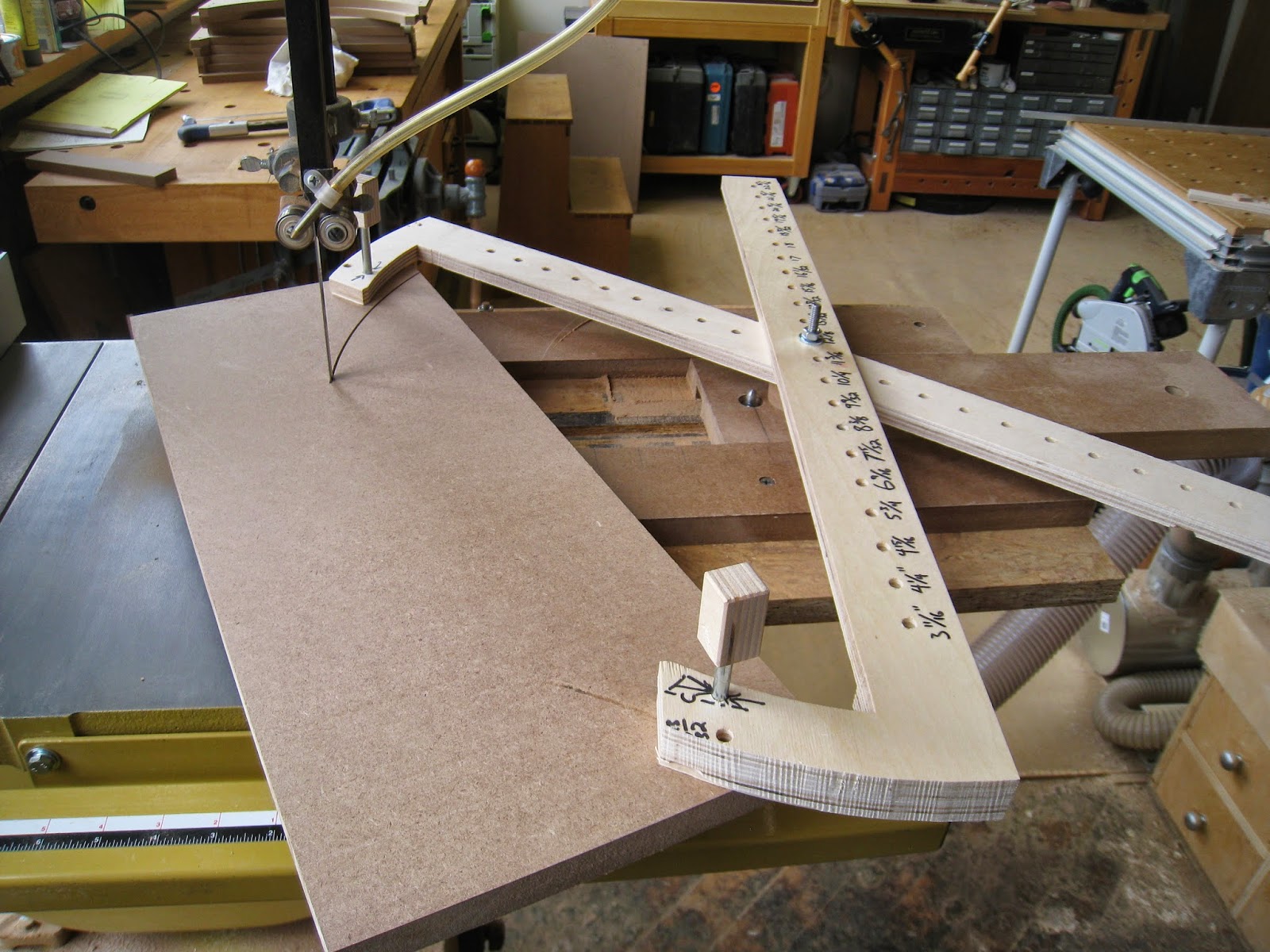
In the picture, you'll also see an arch with a labeled radius. That's one of my radius gauges.
At some point, it became clear that gauging a perfectly concentric arch off of a radius of unknown dimension wouldn't give me the precise results I was after. I needed an arch with a known radius, (radius gauge) to at least make sure the line I'd drawn was at the desired radius. This was when I made the beam compass. With a gauged line, you can see when you've accurately hit your mark. With the jig on the router table, I could fine tune the adjustments well enough to split the mark. (You can see when the knife mark remains in the edge you've just cut.) It's probably not precise enough for a machinist, but it was good enough for me.
Another interesting bit: Without knowing the radius of the edge of this blank up front, using the radius gauge and a center finding head allows me to get a reasonable measurement of the radius anyway. Using the center finding head, I can check to make sure the radius gauge is positioned concentrically. From there, I can measure from the outer edge of the radius gauge, to the outer edge of the curved blank to find out the difference in radii, and go from there.
The outer radius on the arch above (R= 10 1/4") corresponds to a pair of holes on the scissor jig, where the mounting pins drop through. The inner curve corresponds to the next set of holes, (9 9/32" *) which are the holes I used on the jig for this operation. (You can see this in the pictures.) Those holes are centered at a 9 9/32" radius from the center of the pivot pin on the jig. So this was a necessary dimension to gauge where to drill the new holes, for the convex part of the bending form. The arch was an aide to help me make sure that my layout was accurate.
From there, I could set up the drill press to drill symmetrically placed holes...

The holes let me make a concentric cut on the band saw...

...and make the finish pass on the router table.

As Mark had observed, I'd wandered pretty far away from paying work while I was tinkering with this. But as I was tinkering, a lot of things jumped out at me, all at
once, about navigating curves, and I dove head-first into the rabbit hole.
It's one thing to understand the geometry of a circle on paper; radii,
diameter, calculating chord lengths, etc.. It's something else entirely
to be able to create those things in a physical object. It's not a
matter of being able to calculate what the measurements should be, it's a
matter of being able to cut to those dimensions, and be able to
refine the cut to course-correct as needed. This all began to feel like I was
learning to lay things out and plan the process in a whole new way, so I steamed straight on ahead.
There's gold in those hills, if you look for it. But one of the things
I've learned recently from Mark Twain, is that getting the ore out is
one thing, but nobody tells you that refining and smelting the ore is a
wholly separate process, and the finished product can sometimes be smaller than what you think you dug up. Between the beam compass, radius gauges, etc, I burned up a solid day or so in tinkering. The nuggets were pretty shiny, but the final take-away was maybe not as big as I'd hoped. I'm still digesting what
it all means, but I have no doubt that it will turn up in future work, when I
get there.
You can see by the shadows above that the sun was getting low on the horizon by the time I had this worked out.
But the bending form came out cleanly...

And the finished part did, too.

Again, a lot of this is tantamount to driving From Boston to Connecticut, by way of Tokyo. (Which is clearly accomplished by driving a very over-thought car, with re-invented wheels.) Making a bending form is NOT a complicated task, and certainly doesn't call for this degree of caffeine-fueled head scratching. But then again, there are jigs that will come up later on that wouldn't have worked without some of the groundwork laid here.
---

Side note, I wanted to add in here that the MFT was a really remarkable layout aide. Using dogs in the hole grid gave me a way to register parts against each other, or to hold and clamp them at a reliable 90 degrees to each other. I don't think that's enough of a reason to buy an MFT, but if you have one, it's reason enough to invest in some qwas dogs.
* 10 1/4", 9 9/32"... the radii on the jig seem bizarre, I know. I drilled the holes at 1" intervals along the beam,
but the geometry of the dog-leg feature meant that the angles to the mounting holes were constantly changing,
and the radii didn't end up working out to be 'regular' intervals. I'm sure it's possible to design and build a jig to have more 'even' sounding numbers, but at some point, it really becomes academic... or, more academic than this already is. Laying out a part to be cut with this system, means laying out the final radius with a compass, and laying out the concentric radius along which the locating pins would be placed, to make the jig work the way it's designed to. So, I had to measure the actual radii, from the center to the holes on the beams, to be able to lay them out... and the actual numbers ended up being weird ones.