Saturday, December 29, 2012

View from A1

I've occupied my current shop space for just over 4 years now. The whole space is subdivided by pillars, all of which have stenciled letters and numbers near the top. I'm assuming this is for the building owners to be able to reference and specify locations in the (enormous) building.

Anyway, once in a while, I step over next to pillar A1, and take a shot of my bench area, as it exists. And it's interesting for me to see just how far things have come.


Checking out the space. What you can see of the space is roughly half of the length of the building, maybe 1/3 of the width, and this is the 6th floor. We ended up renting half of what you can see.


Early on... Desk in the corner, turned around so I can use the drafting board. Shelves are up, with auxiliary bench underneath, and some old library card catalog drawers under that, which contain everything from random hardware bits and pieces to a complete locking doorknob set, big hinges, string, sharpening stones, extra plane blades... and lots of other things that I have no immediate use for. Shelves were filled with all kinds of stuff, as was the auxiliary table.  Just to the right, under the end of the table, is an old school tool chest with sliding tills inside. A newly built 6' bench is the primary work space, underneath the pendant lamp. Off to the left is a table that supports the grey bank of drawers that's filled with all kinds of odd hardware, and a shaving horse that hasn't figured out where to sit yet.


The big cabinet in the back, to the left, was an initial solution to the sense that I just had too much junk in the work area. In retrospect, storing even more crap in the work are seems like an odd solution. But it is what it is. The desk has been moved out, as I wasn't using it much... even though the drafting board on the back was so cool.


The space starts to hit critical mass. At this point, I've moved the big Sjoberg bench in from the machine room. The auxiliary table is off by the window, and is storing unfinished projects. The old tool chest is underneath. To the left of that is a filing cabinet. Corner bookcase now holds my NBSS tool chest, and the library card catalog full of random stuff, and a pile of other things I don't usually use. Patterns are on the wall next to it. The grey drawers are in the tall cabinet, and the table that used to support them is under the shelves, next to a plastic set of drawers that serves no obvious purpose. The shaving horse is still running wild. I have almost everything I could possibly need to do almost anything... except for space to do it in. 

The exodus of stuff has begun. The shave horse and the old tool chest have been exiled to the loft. The auxiliary table has been broken down and stored. The Sjoberg bench is next to the window, with the (blocked from view) filing cabinet still by the window, and the general floor plan is much more open... open enough to build something like this bookcase. The big cabinet has been moved to the right of the shelves at this point, and the shelves have been shifted to the left. They're still full of stuff. 

The open floor plan is well established at this point. The tall cabinet has been moved into the back corner of the machine room, as I've realized that anything I'm not actively using (hardware, misc junk) doesn't belong in my active work area. Well, except for the patterns that are hanging above the desk, which returned from exile as I began to realize that a) it's still a cool desk, and b)that I need to actively organize the work that's done on the bench, and the work that I need to do to organize the business. The filing cabinet's contents are in the desk drawer, and the filing cabinet is gone. Shelves are now mostly empty, so that I can use them for projects that are in motion.
 

The current Logjam... This project will be on its way out the door sometime soon. It has definitely tested the limits of my open floor area... and slabs that big and thick are HEAVY, which has meant that moving them around was something that I just didn't feel like doing, even as I tried to work on other projects at the same time. For the most part, everything in the frame is something I have regular use for, or something I'm in the middle of working on.

Things continue to evolve...

Friday, December 28, 2012

Rockler Glue Brush Update

Again, I'm not a corporate anything. But the Rockler glue brush has continued to perform as advertised, which is something I rarely find, especially in woodworking specialty stores these days. It's very easy to clean.

I was in the store the other day, and found that they have released a smaller version, which was pretty much the only improvement I would have wanted. The standard version is pretty big. There are tasks for which it is very well suited, (both ends, at that... the paddle end is great for spreading glue on Festool Domino tenons) but there are also tasks for which is feels a little ungainly. The new version has a small brush, and a nub on the other end for working glue into tight corners.

I have an upcoming project that will involve more joinery, so we'll see how well it works when I get that far.

Thursday, December 27, 2012

The Dremel as a router


I spent a lot of time inlaying butterfly joints in the slabs this past week. It's a lot of material to remove, and this project has been lagging, so I decided to go with the less traditional methods of waste removal. I drilled out holes with the cordless drill, and then proceeded to handle waste removal with a Dremel tool mounted in the router base that's made by Stewart MacDonald. The butterfly joints go pretty deep, so I went with one of the high speed spiral bits to help handle trimming, since the cutting edge is full length, and they're long enough for the job.

As a hand tool purist, I would be disgusted with myself if it didn't feel so much closer to a hand tool in use than a regular router does. It's slow and steady, pretty controllable, and because it's underpowered, (and because it was cutting through an inch of walnut) it offered more tactile feedback than a regular router would: A full-strength router might buck just enough to let you know it ruined something as it goes by, but not necessarily. So I'm pretty happy with this setup.

There's only one real problem, and it's the reason the ear muffs are in the photo. It sounds almost exactly like this:


Wednesday, December 19, 2012

Shop update

Still loving the Japanese chisels.

Thursday, December 13, 2012

Simple Shop Jig of the Day

Just a fancified stick with a ruler on it.

Way back when, I was setting up my crosscut sled, and didn't need the first six inches of stick-on metal tape. There are other jigs where I took a big chunk off the back end of the tape, that works, too.

The point isn't to take a measurement, though. I have a lot of jigs and setups that require little more than a clamped-on block as a reference stop on one end or the other. Inevitably, it needs to be moved by about 'that much,' to complete the operation.

In this case, I'm referencing a notch from the end of the stick on the router table, for some coped window muntins. Too much off the stick, and the part will be too short.

Now I can see, based on the scrap of scale that's glued to the block, just how much I'm actually moving the block when I adjust my reference stop. It made this particular operation much easier, and more accurate than using pencil marks.

Why So Serious?

I was having a conversation about shooting boards today. Some folks just go too far with the fancy.

There are times when I might go for something with a much longer fence, but for day to day, this one does just fine. The 90 and 45 are accurate, but short enough that a little bow in the molding won't ruin your day. The whole thing is small enough to be easily put away.

Low angle jack plane has mouth wide open, but blade set for minimal projection. That lets it take big bites down to 45, but make fine adjustments when care is needed.

Monday, December 3, 2012

Planning tool: small drafting board


I get that sketch up is becoming a thing, I get that computer drafting tools are very robust and efficient once you get the hang of them. But I'm a traditionalist, and there are times when I think that drawing things out by hand is more useful. Because it's a physical exercise as much as a mental one, the process of drawing out the details of a project engages the mind in a different way than CAD or sketch up does: You have to fill in the details by hand in the drawing, nothing is automatically generated. And as you put those details down on paper, you have to work them out in your mind. It's the shortest route I know to really wrapping my mind around a project.

I know from experience that many people have the same attitude: "I can't draw." The whole point of a drafting table, or a board like this one is that you have rulers and square edges to guide your pencil. You don't have to be a skilled fine artist to make a drawing of a piece of furniture. Some drawings are more involved than others, but the whole point of drafting in the first place is to build the piece on paper, first. The drawing is a place for you to work out the kinks of the design, and it's a representation of the physical object that you aspire to build. If the details of the drawing are too complicated for you to puzzle out, then constructing the actual object probably is, too.

Making mistakes and erasing them on paper is much easier and cheaper than making your mistakes in wood, and the simple truth is, we learn from our mistakes, and we learn from struggling with a topic. If you don't always have time to spend in the shop, or money for wood, time spent drafting new designs will be well spent, and allow you to spend time solving the puzzles ahead of time.

When I went to school, we had large, 40" x 5' long drafting boards for doing full size drawings of furniture. I have one at the shop that's 50" x 6', and it's great for that. But not everything demands that much real estate, so I came up with this small board, that's great for working out individual details, or doing small, scaled drawings on regular 8.5" x 11" sized paper.


It's just a small piece of MDF, with vertical and horizontal reference edges along two sides. These edges need to be square to each other, but other than that, there's not a lot of time or skill that needs to be invested in this project, which makes it great for beginners, both as a small project, and as a tool to help them plan out larger projects. It's very simple, very inexpensive, and all you need to make use of it is a pencil, and a drafting triangle or two. It's perfect for doing some quick head-scratching, and working out how something will go together. And I feel a lot more comfortable using this in the shop, than I would an expensive laptop.

At some point, I'll make another one to use at home. When I do, I'll probably make it wider, so that I can reference more of the triangle's bottom edge when I'm drawing vertical lines on the right side of the page.  Chances are pretty good I'll simply make a square version.

Shop drawing for a door, with stock list along left edge.

Tuesday, November 27, 2012

Spiers plane re-assembled.

Per Konrad's advice, I got set up to drill the shell and the infill for bigger pins. This is where things took a turn.

I clamped the infill into the plane, clamped the plane in the cradle, squared the sole to the drill press table, and drilled the first hole. And if the original hole had been oriented this way, things would have gone better. (No, I didn't check.)

In the picture, part of the problem is pretty obvious: the holes don't line up on the exit side. What's not obvious is that because the bit didn't squarely engage the inside of the second hole, it shook a few things up, and the infill shifted in the shell during the procedure. So the hole through the infill was not as clean as it should have been, and when the pin was inserted in the resulting hole, it pushed the infill up, and out of alignment with the shell. I had to file the hole in the shell a little bit, and file the hole through the infill a lot. What eventually I figured out that setting up the iron would help. The lever cap clamps the iron down to the infill... and clamps the infill down, in this case, to the shell. So I did that, and chased the hole with a cordless drill. I had to insert some bits of wood into the infill to patch the hole and get everything to line up, but the end result worked fine.

I have to admit, it was hard not to succumb to the 'Oh, no, all is lost,' feeling that I had in the moment. But it helped knowing that the plane was not immaculate to begin with, and to know that a repair was (almost) always possible. 

Setting up the iron was a minor issue. The patch for the handle shifted its position a little bit, and the iron came to rest on the end of the handle, instead of the bed, so I needed to reshape the handle.


For the second pin, I did everything with a cordless drill; drilled into the shell, chased the hole through the infill, and drilled back out. Much easier.

Peining the pins wasn't too hard. It would have been easier if I had a real anvil, or big block of steel to work on... maybe a chunk of railroad track or something. But no, all I had was this cocked-up wad of self-delusion. --->

It worked, for which I'm grateful. But a 4 lb hammer clamped to the bench is not an anvil. I'm gonna have to find myself an anvil, or some old, abandoned railroad track if I'm gonna keep doing this kind of thing.

I should have taken more pictures of the peining process, but truth be told, it was pretty nerve wracking, and I was more worried about getting my favorite plane back to normal than I was about sharing the train wreck experience. For a while, it just didn't feel like it was going to happen. The wallowed out hole just wasn't filling up, the pins were feeling loose, and the infill felt like it was loosening in the shell. In the end, everything snugged up just fine, which was a relief. But it was pretty obvious, pretty quickly, that making infill planes involves several skills that could be developed a lot further. Cutting pins to proper length, drilling a better hole, reaming the hole the right amount... if reaming is even really required... there are a lot of small factors that would very clearly make the whole process a lot smoother and faster.

After everything was put back together, I had to give the plane a good going-over. One side of the bed, despite my best efforts, was still a little bit high. And all of the peining had distorted the sole by a thou or two... enough to prevent me from getting a good, full width shaving at the finer settings. But these weren't too hard to remedy. I may still need to tweak the plane a bit here and there, and I do need to touch up the finish.  But it's done, and it works.

The whole re-assembly made me feel like a rank beginner... which was uncomfortable. But I AM a rank beginner when it comes to this kind of work. The point of the project was to get the handle solidly re-attached to the rear infill, and the handle feels solid now. And the plane still works. So even if it wasn't what I consider an expert repair, it was successful. Considering that I regularly use this plane, and don't need a conservation-level repair, that's good enough for this go around.


Monday, November 26, 2012

A grand experiment

So, for about 6 months or so, we went without the Internet at home. It was mostly an extension of our TV-less lifestyle, which has stuck very well. We do watch DVDs on the laptop when we feel the need, but the habit of plopping down, and mashing the remote for an hour an a half with the mantra  'There has to be something on... 100 F****** channels... There has to be something on...' is long dead.

The basic logic behind disconnecting was, we both have iPhones, so we had basic access to information and email. She had web access at work, I could use wifi at a local coffee house for blogging, and either way, it would feel less like a mindless plug-in. I think that on the whole, it was a good experiment. I took some getting used to, but it definitely made clear that the Internet had simply been providing a new outlet for mindless time wasting. And I'm trying to be more conscious of where my time goes these days.

There were a number of factors that led to re-connecting. First and foremost, there are some required things that really require Internet access... Working with banks, emailing documents to insurance companies, even allowing doctors to access medical records... Internet access has become as necessary as the telephone. There are certainly work-arounds if you don't have it, but it was cramping our style.

Among other things, it really torpedo'd this blog. It's not so much that you can't blog with an iPhone, you can. But it's not the same as having a real keyboard. That, and google decided to update the blogger interface, and they don't bother supporting Safari anymore. It's marginally functional, but working with links, adding more than one phot, etc, was problematic at best. 

The upside is that I'm now more practiced at phoning in short updates from the shop, like the recent posts about the Spiers plane. But now that I'm back online, I'll be able to get back to writing longer, more thoughtful pieces again. 


Wednesday, November 21, 2012

The road to recovery (Spiers plane rehab update)

Tending to business has kept me away from this side project. Here's where things are right now with the coffin smoother.

In the photo, you should see a few things:

-A wedge that is now firmly glued into the underside of the infill.
-The tapered tongue on the tote that has made the wedge necessary.

The tongue was cleaned up the other night, and everything fitted together. I glued the wedge in last night, but the tote didn't fully cure, so I'm re-gluing again today. This is one of the great things about hide glue... It will give you second chances. And, according to the paper that came with my glue pot, it will forgive up to 1/16" gaps. Good news all around.

It will also give you stinky fingers, but I digress.

The shot above should also show a few other things, such as

-It's clear they used something resembling a dado stack to run the groove in the infill. That implies uniform depth, which is why the tapered tongue was problematic.

-Paper shims. These planes were NOT immaculately made. That doesn't mean they don't do a damn fine job. But that element of human error is reassuring to me. It tells me that nothing is perfect, and mistakes can be corrected without diminishing the end result.

I like that. This was the best performing plane that I owned before I cracked it open, and I was really worried that I'd mess that up in the process of fixing the handle.

Coming up after Thanksgiving, I get to clamp in the repaired infill, drill new holes for 5/16" replacement rods, (Per Konrad's advice) ream the holes, put everything back together, and pein the new pins.

After that, it's the slow, arduous task of filing, and cleaning everything back up.

Tuesday, November 13, 2012

Infernal smoothing plane obsession. Or, 7.5 years later.

It seems I've gone through a smoothing plane growth spurt lately. I'm still settling the collection out after this summer's discussion of the Kato/ Kawai chip breaker study. Two infill planes came screaming into my favorites list after lingering for years. And today, I had the thought to revisit my Japanese planes.

The chamfer plane was first, and was the banana peel that got this afternoon's ridiculousness under way. (This, after I had to reset jointer knives this morning.) The blade was in rough shape, and I remember reading about the blade preserving effect of a properly set chip breaker.

Given, sharpening always gives the most and best improvements, but I figured I'd try the chip breaker out, too, since the plane did come with one. Once it was set, the plane handled grain reversals in soft maple very, very easily. Second banana peel...

My Japanese smoothing plane hasn't really been used much since I bought it for a class 7.5 years ago. But after my success with the chamfer plane, I pulled it out of the storage closet, and re-installed the chip breaker pin.

Once all of the parts were sharpened and tuned, I set about re-acquainting myself with the plane. It took some time to get used to hammer-adjusting the chip breaker separately from the blade. But within half an hour, I was taking sub-thou shavings, easily. And I also came to understand that the chip breaker doubles as a wedge to really lock up the plane, once it's properly set. The other side effect of this is that a more tightly held blade moves in smaller increments when it's hit with the hammer. Finer adjustments are never a bad thing...

So, the Japanese plane is going in the drawer with my other actively used planes. That makes 7 smoothing planes. I seriously have a problem. Is there a 12-step program for hand plane junkies?

I bet Chris Schwarz would know...

Monday, November 12, 2012

The compound evolution of jigs

This is a simple enough jig in theory. The idea is to center a domino in the middle of a louver that will be part of a radiator cover. The mortise is centered in the stock thickness thanks to the Domino Plate that Ron Wenner made. (A search on this blog + Ron's name will take you to those entries)

Width-wise, the block that cradles each louver is cut to fit exactly (+/- a couple of thousandths of an inch) between the locating paddles on the Domino. To make that happen, each side piece was ripped on the table saw with the micro-adjuster that I made.

They say that practice makes perfect, and that it will get you to Carnegie hall. In this case, jigs made to allow me to be more precise have led to other jigs that I couldn't have made otherwise. Skills build on skills, tools and jigs build off of what came before, and today, I can do things that I literally wouldn't have been able to do a few years ago.

Tuesday, October 30, 2012

Why I love the internet, and FOG

The Festool Owner's Group saved my sanity today.

I won't get into technical details, but the short version is that I own two Festool track saws, the big one and the regular one. I bought the big one used, and it wasn't properly adjusted. I was trying to trim the ends off of the slabs today. The blade was deflecting, scorching the wood, overheating and dishing (ruining) the blade... Deflecting to the point of nibbling at the saw housing. When a tool is causing damage to the project, and to itself? That's bad. It needed help.

FOG to the rescue, saw works great now.

---

I was talking to someone the other day about Festool, and their complaint was that much of the system isn't intuitive. This from a woodworker who rebuilds his land rover as a hobby when he's not raising two daughters... Like any of that is intuitive.

There are many things in woodworking that seem intuitive and simple. And they are, to a point. But doing them better... Sharpening, sawing, layout, hand planing, chiseling, working more productively, and on, and on... Getting better at almost anything, is not intuitive. So, it helps to have a tutor for some things.

I hate the Internet for learning things a lot of the time because it's a bottomless, shifty morass of unreliable information from professionals, novices, hobbyists, and 50 year old men posing as underage girls... And it's just as likely to ruin your mind and your day if you give in to it.

But if you come in with a specific question, within specific boundaries, a bit of a knowledge base, and you don't mind taking the time to UNDERSTAND what the proposed solution is, it can be miraculous, and help you get past those things that aren't as intuitive as we'd like.

My $500 circ saw is now cutting cleanly. It's not scorching the ends of a $4000 slab of walnut, and it's not causing $75 blades to overheat and self-destruct. That makes me happy.

Wednesday, October 24, 2012

Thursday, October 18, 2012

Stupid little jig of the day


It's just a block, on a bolt, to support a long piece of wood while planing. But what a difference it makes.

And if Chris Schwarz ever reads this, he'll curse me for a nincompoop, and say something tantamount to "No $#%¥, Sherlock! I told you about that in a work bench lecture 5 YEARS AGO!"

Spiers Repair pt. 1


So, the infill is out.

I whined to Konrad that it was a great little plane and why couldn't I just inject it with glue... But he was right... And I'm glad it's out. As it turns out, the tenon on the handle is tapered in thickness from top to bottom, and it really didn't fill the slot that way, which is why it was wiggling. No way a glue injection would have solved that.

Back to work... I have things to get built today.

No Guts, No Glory

Wednesday, October 10, 2012

Tuning up an infill plane

Crooked lever cap in the Mathieson
I know that infill planes have a reputation for being the Wood God's Harbingers of Immaculate work. The truth is that they are just as susceptible to hard wear and imperfection as any other tool that was created or used by man. 

My first infill plane was a dovetailed steel Mathieson smoother that I’m still having problems with. It took me two years to notice that the lever cap had been installed at an angle to the bed, and four more to notice that the screw for the chip breaker bottoms out in the groove in the bed. And the sole isn’t flat, or at least not flat enough.

The Musgrave was the second plane that I bought. It has a cast iron body that’s chipped on the back corners. The sole needed some flattening, but cast iron is soft, so this was easy to do. Once the sole was flat, I was able to use it, and to start learning just what these planes can do.

When I was just starting out as a woodworker, I learned to tune up Bailey style planes by working on Record and Stanley smoothers. Those are more straightforward: most of the work has to do with making sure the sole is flat, and that the parts are mating properly. Infills generally have no parts to take out, and no obvious interfaces to refine, so it took me a while to notice the subtle things that need to be attended to. Of the three infills that I own, the plane that has taught me the most about tuning up an infill plane is a dovetailed steel coffin smoother from Spiers. So I’ll describe my experiences with this plane, to date.

I started with the obvious: sharpening the blade, and tuning up the chip breaker. That led to me discovering problem number one: neither was squarely ground. I was a little surprised to see that, but it was easily resolved.

Once the blade assembly was ready, and I went to install it in the plane, I started having issues with lateral adjustment. Eventually, I noticed that the screw for the cap iron was way too thick; it was bottoming out in the groove in the bed. Apparently it’s not an uncommon thing for old infill planes to be paired with replacement blade assemblies, even if the screws don't fit the groove. So, that's why the discrepancy existed. (Noticing this on the Spiers led me to notice a similar issue in the Mathieson plane, too.  The discrepancy isn't quite so egregious, but was just as problematic.) Once I ground the screw down, the Spiers plane was a lot easier to set up and adjust.

That said, it wasn’t really taking good shavings. It took some inspecting to realize that the sole wasn’t flat. In fact, the surface in front of the mouth was not at all in the same plane at the surface behind the mouth: It was almost 1/64” off. Steel is much harder than cast iron to lap flat, so I had to take the plane to a belt grinder to (carefully) get the whole surface to be approximately co-planar. At that point, I could take shavings with it, but once I started dialing the thickness down, the shavings only came in at the corners of the iron. What that told me was that only the corners of the blade were engaging, and the middle of the sole was bellied out by roughly the thickness of those shavings. I flattened the rest of the sole with a file, and a machinist’s straight edge, until the shavings were perfect. This took some time.

With the blade sharpened, and the sole completely flat, the plane started functioning at a very high level. So all that remains is repair to the body and tote.

There was a crack in the handle. The other two infill planes I own each have a screw that is driven up into the handle to reinforce the rosewood. But Spiers used a steel rod, and I couldn’t thread it back out. The cracked handle was holding together just fine, but it was flexing, and needed to be fixed. It took me a while to figure out a viable repair: I used a dovetail saw to turn the crack into a saw kerf on each side of the handle, and then I glued a piece of veneer into those kerfs. Once the glue dried, there were no more gaps to allow the handle to flex. That said, the handle was still moving in relation to the rest of the plane, though.

At this point, I sent an email to Konrad Sauer. He asked for pictures, and pointed out that most likely, the handle had separated from the rest of the infill, and was pivoting around the rivet pin. When I got back in to look at the plane, it feels like this is exactly what’s going on. The options I have are to flood the cracks around the handle with glue, and hope it works, or to drill out the cross pins, pull the infill, and reconnect the handle. That’s where the process has taken me to date.

----

I emailed Konrad back and mentioned that I was writing an entry about tuning up infill planes. I mentioned all of the above to him, and asked if he had any extra advice. This is what he said:

"The usual issue with an infill is the bedding. Most of the time, the bed of the plane is not coplanar with the metal block that is rivetted to the sole. This means the blade rocks or pivots on that point. Doomsday for trying to set the iron. The first thing to check is the bed. If it is flat (they rarely are) then you are in for a tedious PITButt job of finding a narrow file that has safe edges to get in there and re-establish a flat bed. All the time trying not to touch the leading edge of the mouth or the lever cap. And... you have to do this evenly because of you change it too much, the blade will sit differently and the front edge of the lever cap will no longer contact the top of the cap iron squarely. So now you have to either continue re-shaping the bed, or... file the underside of the lever cap. The best way to do all this is with the lever cap out - but that means pulling more pins. This task is by far the most challenging task - all the others are way easier. "

Given the importance of properly bedding the blade, and given the importance of the alignment between the infill and that metal block, I'm seriously thinking I should try for the glue injection method, as it seems easier, and not pulling the infull seems less likely to result in a misalignment between the bed and the metal block.

Konrad may have a good reason for having me pull the bed. And truth be told, I'd like to have the experience of pulling the plane apart. But I'm not sure that a little handle wiggle is good enough reason to take apart a plane that's working so well right now, if a simple glue squirt will fix it.

So, we'll see...


On Infill Planes (Part 1 of ?)


I like to promote the idea that good work can be done with humble and simple tools. So, talking about infill planes feels a little disingenuous. Recent experiences have taught me that while both humble and fancy tools can both be made to do good work, some tools make it a little easier to do.

My first infill plane was a Mathieson coffin smoother, with a dovetailed steel body. A couple of years later, I bought a cast iron Musgrave infill (possibly made by Norris?) and a Spiers coffin bodied smoother that is slightly smaller than the Mathieson. Both have required work to get them functional, and I’ve learned a lot about tuning up infill planes from them. (These are the two in the photo above)

I'm aware that infill planes have a certain aura. New infills can cost more than a decent used car, and the more notorious builders have impressive reputations for precision work. And to hear some folks talk about the older models from the British Isles, you’d think they were magical instruments, carried down from the days when gods and monsters walked the earth. What I’ve learned is that they’re not. They’re just as subject to wear and imperfection as any other tool that was made and used by the hands of man. Once they’re properly tuned, and once you’re used to setting one up, infill planes do make it possible to easily make very minute adjustments to shaving thickness, and allow for more accurate surfacing to be done. I'll talk about tune-ups in the next installment.

The Musgrave plane taught me the most about setting up an infill plane for use. I tried setting up with the blade short of the mouth, and using a hammer to adjust it to the desired setting. But eventually I realized that I could just loosen the lever cap, let the blade assembly sit on the bench, slide the plane slightly forward to bed the iron, tighten the lever cap, and work. It’s very fast, and requires no other tools to set up this way.

After using it for a while, I realized that the lever cap also doubles as a very fine depth adjuster, and it doesn’t need to be heavily cranked down. Whether this feature is by accident or design, I have no idea. But because the lever cap is built as a lever, and multiplies the force that’s applied by the screw, which is also a force multiplier, very light pressure on the screw will hold the blade pretty firmly in place. If the pressure is too light, it’s easy to knock the blade out of alignment, but it’s not hard to find the tension sweet spot with a little practice. Once the plane is set up, the lever cap has enough force to slightly affect the projection of the blade from the bottom of the plane, and make those delicate (sub-thou) adjustments I was talking about. With time and practice, setup and adjustment of an infill plane is much faster and easier than on a Bailey style plane.

In recent work, this adjustability has helped me to shape blanks more precisely than my power jointer or planer would allow. At the time I was putting together a complex compound miter joint with large surfaces, so accuracy was more important than normal. Because the adjustment on an infill is so precise, (using only the lever cap, I don’t have mechanical adjusters on my infill planes) I was able to take much finer shavings, and get the blanks accurately square and reference-flat. This in turn allowed me to make more precise cuts on a sliding table saw, thanks to the ability to reference more accurately against the table.

Infill planes do need to be very well tuned. It took me a while to understand what that meant. I’m used to Bailey style planes, and while Bailey style planes have many areas that need to be tweaked, tuned, and properly fitted, these areas have been described in detail in many publications, they’re more obvious, and more accessible. Infill planes are a lot more subtle. The entire assembly is one solid unit, and when there are no obvious assembly points to tweak, it’s hard to figure out what can be done... and what needs to be.I'll write about that in part 2

Tuesday, October 2, 2012

Happy Customer: Rockler Glue Brush

I can't honestly say how much glue I've wiped off of my fingers onto the underside of my bench. But it's a lot.

I've tried acid brushes and popsicle sticks, and other disposable things that inevitably don't get replenished, or at least, not in time for the next glue up.

I picked up this little gem a few weeks ago. The silicone brush clears so easily once the glue dries, if's almost self cleaning. And the paddle makes obvious sense for glue spreading.

I'm not a corporate subsidized anything. I just thought this was worth mentioning.

That said, I haven't used it with hide glue yet, and hot hide glue's on my short list of things to introduce into my work flow. Still, I don't foresee many issues.

Thursday, September 27, 2012

Simple procedures

It's funny to me how complicated the simplest procedures can be sometimes.

In this case, I had to cut an arch for a detail piece on a built in that I'm installing soon.

First, I had to consult the Internet to remember formulas for chord length. I knew how long the chord length was, I needed to use that to chase back and find the radius of the arch. The radius I came up with was 15' 6".

Then I needed to make a trammel beam that would hook to my bench on one end, and mount to the jigsaw on the other.

Fifteen and a half feet is a long distance for an unsupported beam, so I brought out the trestle rails.

Last but not least was sawhorses, and a box beam to clamp to.

In all, about two hours of setup time. Two minutes later, the cut was done.

Saturday, September 22, 2012

Cutting dados with the cutting table

Using routers with guide rails is nothing new. But I like this setup for two reasons. If you want to run dadoes at a fixed distance from one end or the other, this is, again, easier than a table saw. And, I find the depth with a router cut dado to be more reliable than with a table saw. Sheets flex, it's hard to keep them firmly down. And cross- cutting dadoes with a table saw on long pieces like this requires either a really big sled, (ie, bigger than mine) or alternate but similarly excessive techniques. So, this table is great for production work in that direction.
Another little time saver is this router starting block. This is the first piece that gets cut with the router on the first pass. It tells you exactly where the router will enter the wood. Simply align your layout markings with the actual cut, and go. That saves a LOT of time that would otherwise get tied up in fussy measuring techniques. Good stuff. And, again, this doesn't have to be quite so fancy. Using something simpler for the rail, and routing with a laminate trimmer would work, too. And the top picture above shows a simpler production fence than the Kreg setup: just some plywood and a clamp. I went with the Kreg because I think it's more robust and precise, but hey... Whatever works.

Cutting table Part I
Cutting table Part II
Cutting table Part III

Thursday, September 20, 2012

More on the cutting table

I pulled out my DW circ saw to demonstrate the point that this table isn't just for Festool junkies. It's for anyone who needs to break down sheet goods cleanly, to reliable, repeatable dimensions, but don't want to use a table saw, either because...

-They don't have room for in feed and out feed in their basement shop.
-This whole setup is cheaper than a table saw.
-Moving a circ saw over a table is easier on the back than moving a full sized sheet of ply, and more controllable.

I've seen methods for making a zero clearance plate for a circ saw. Some involve bolting on a piece of Masonite, or filling the plate with bondo. However you do it, with a zero clearance plate and this table, the veneers on both sides of the sheet will be supported. That means you can cut a finished edge in one pass.

For my next trick, I'll be using a router with this table, to make identical dadoes in multiple pieces...

Cutting table Part I
Cutting table Part II
Cutting table Part III

Tuesday, September 18, 2012

Festool cutting table

A couple of years ago, I got a look at a cutting table over on the Festool Owner's Group message board, and I thought it was really cool. I bought a bunch of plywood to build a version of my own, but I stopped short. I looked around and realized that what I really wanted was the space, not more stuff, and so I shelved the idea, until now. The main difference between what I had planned to build then, and what I actually built today, is that this is just a work surface, not a full table. We have a 4x8 assembly table/plywood cart in the shop already, and eventually I realized that I could simply make an MDF top, and put that surface away in the plywood rack when it wasn't being used.

The idea is simple: the Festool track registers against two points, that hold it square to a fence that's equipped with a production stop and a ruler. So, rather than measure and lay out every piece, and clamp the fence down for every one, I can set the stop and make the cut. Done. And because the MDF is supporting the underside of the sheet, the veneer doesn't get ripped up so badly.

The reason to make this is simple, for me. I have a lot of 8' long pieces of plywood that are too wide to fit in my cross cutting sled. They're destined to be cabinet parts and shelves, but they need to be cut to length, and that with efficiency. Given the half a day that I lost throwing this together, the efficiency part may not be in evidence on this particular project, but I suspect that future projects will vindicate my decision.

For the average woodworker with a 'normal' circ saw, this is still something that can be approximated. There are clamp-on guide fences that can be used instead of the Festool track to do basically the same job. If you use a lot of sheet goods for production jobs, this might just save you some time, and make things easier on your back...

Cutting table Part I
Cutting table Part II
Cutting table Part III

Monday, September 10, 2012

The chair is finished...

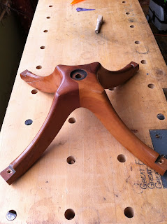
Well, it's been finished, I just hadn't had time to post it. The base finished up nicely, and refinishing the rest of it turned out well.

I'm really grateful to have had this project. One of the interesting aspects of cutting the semi- mitered joinery was that there was a LOT of precision involved. In the end, the blanks were out of square just enough after the jointer, planer and table saw, that the sliding table saw wasn't able to cut accurately enough. I needed a hand plane to get the blanks to be just so,

After that, all of the shaping work reminded me of just how skilled I am, and how much I'm able to rely on my hands when the limits of the ability to work accurately with machines is reached. Cool stuff.

There was a very strong element of 'be careful what you wish for,' in this one. I've had a yen for complex curves and complicated methods for a while, and, well...

:-)

Wednesday, August 22, 2012

The Cadillac Man has left the building...


Even after spending as much time as I did on tracing a 3-d shape into 2-D patterns, and even after all the time I spent getting the mating faces and miters cut perfectly, shaping this chair base has turned a lot of things upside down. The entirety of the thing is made up of complex curves, but there are ways to lay those out, if you have precise reference surfaces to work from. But once I'd sawn rough shapes in two dimensions out of the blanks, there wasn't a lot that I could do to hold everything in place on a router table or shaper. That's not to say that I didn't try, but the harder I tried to force the process to work, the less it worked. I had roughly sawn blanks, but I couldn't get the precise reference surfaces that I wanted.

14 years ago, I worked for a company in Houston that provided Remote Operated Vehicles for offshore use in the Gulf of Mexico, and around the world. The vehicles were basically robotic submarines, connected to the ships and/or oil rigs with long tether cables, and piloted by operators on the surface. Operators 'flew' these remotely operated submarines remotely, and operated the robotic arms when required. Some of the more advanced models had various functions that are roughly analogous to cruise control, including a position holding function. Because he loved his cruise control, and the ease of use that it allowed him, one of my co-workers leisurely announced one day that "I'm a Cadillac Man, you know?"

One day, a job called for more accurate position holding than the computer could really handle, given changing currents and computer processing speeds. (This was 1998.) Cadillac Man told the boss it couldn't be done. Someone else stepped up, and said he thought he could pilot the sub well enough to do what had to be done... And so he did. Cadillac Man left the control room in shame. He'd traded aspiration to skill for reliance on machines.

I spent so much time messing around with patterns, figuring it would be easier for me if the machines could give me the reference surfaces that I wanted. I wanted identically smooth surfaces, and I didn't want to have to make them myself. This, despite my years at North Bennet, and learning how to do things by hand. And finally something snapped. So I pulled out the drawknives, and spokeshaves, and commenced to make a hell of a mess... and to shape some very attractive chair legs.

 I gave up on the notion of doing this with precision, because the truth is that even if I'd gotten precisely milled surfaces, there was only so much that this would give me,  and sometimes the only way forward, is 'blindly, with doubt and faith.' (I'm NOT the religious type, believe me.) I remember thinking to myself 'Elvis has definitely left the building on this one...' But at the end of the process, it was actually a lot easier, and a lot more controllable.

The not-quite epilogue... I spent part of today sanding down the new legs for the chair that I'm rebuilding. They look good. There are spots here and there that don't look perfect to me, but I'm a neurotic perfectionist sometimes. That's why I'd rather leave it to the machines, it's less nerve wracking. I say not quite, because there are still a few things that need to be done, including inserting dowels into the legs to re-distribute some of the interior stresses, drilling for the seat post, and notching the ends of the legs for the hardware. 

Friday, August 3, 2012

Head scratcher of the day


This week I've been making a new base for an Italian-made office chair, as the original legs are splitting. (Bad hardware design.)

The base is made of four saber legs, joined in the center with some really funky nonsense. Basically, two opposing legs butt-jointed, end to end, but at 30 degrees to horizontal, I'm presuming with dowels inside to hold everything together. (That's how I'm gonna do it, anyway...)

And then two more coming into the side, with a weird half-miter, again at 30 degrees. 

So, the drill is, mill the blanks, and cut mating surfaces while there are still reference surfaces to use, drill for joinery (dowels) and then shape.

It's taken the better part of a day and a half to get the mitered surfaces cut...

Oy.

Shaping starts next week.

Tuesday, July 31, 2012

Pattern tracing tool


I'm in the middle of a repair that calls for new legs, and they need to be identical, which means pattern work. But there are some compound angles and curves involved, so tracing patterns requires some trickery.

I won't go too far into the logistics, but having one of these helps. Basically, it's a straight edge that comes up at 90 degrees to the surface that it rides on, and at the bottom of the edge is a mechanical pencil. So, regardless of where the object is, above the plane that the pattern is traced onto, the projected profile will be accurately traced.

And yes, that's a Miller dowel being used to push the button on the pencil. Miller dowels! Oh, the shame!