Showing posts with label Hybrid Woodworking. Show all posts

Wednesday, December 18, 2013

The Hay Rake table round up.


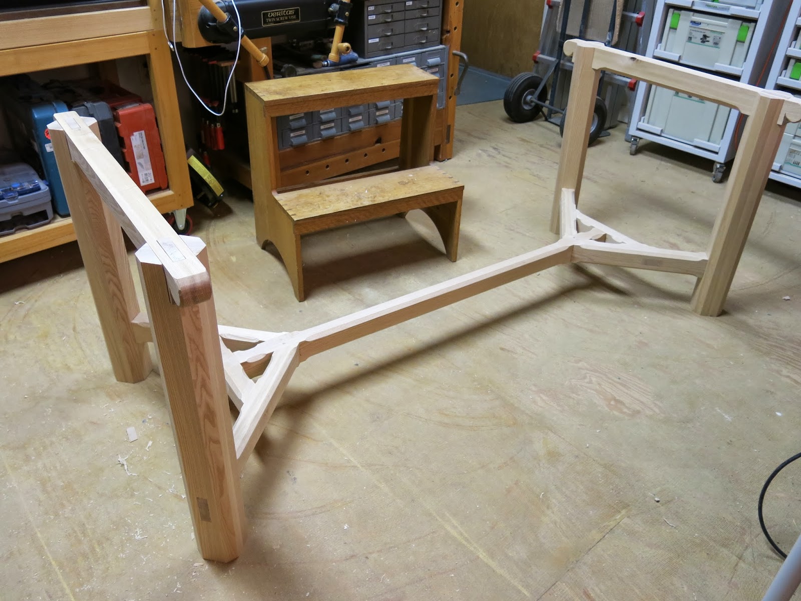
I had a lot of fun with this project. The joinery was challenging. (There will be a post-script on the stretcher joinery soon.) The fact that I built it without a table saw put an interesting twist on the process. Using the drawknife put a goofy grin on my face. I really liked the finished piece. And in the end, the client was happy with the end result, which is what's really important.

The structure of the base is very interconnected. Four pieces come together simultaneously at each end of the stretcher bar, and the resulting geometry determines the position of the legs. (I'll do a post script soon about how the joinery comes together.) The legs each have bridle joints cut into the top that capture the cross bars that support the table top. They also have tenons in the middle of each bridle joint that go through those cross bars, which locks everything together. The corresponding mortises have to be cut accurately, or they'll mess with the leg position, which will keep the stretcher joints from closing fully. Or, if the joints don't close, the legs won't join properly to the cross bars. Everything has the potential to mess up everything else. But when it all comes together properly, the resulting whole is a stout, strong piece of furniture.

Working with reclaimed lumber was interesting, and eye opening. It's pricey, and full of nails. That said, the aesthetics of the spruce caught me off guard. I don't normally go in for the rustic thing, but the boards were beefier than normal, from a pre- home center age. And they felt pretty dense for spruce. All of that, combined with the base, came together as a finished piece that really grabbed me. And I had to admit to the client that I didn't really want to give it to her. (I only admitted this once it was in her dining room... there's no sense in worrying people unnecessarily.)

I'm a big fan of Barnsley furniture to begin with, but the potential that his style represents for the way I want to work is impossible to ignore. The joinery is stout, but straightforward. The chamfering looks great, and is an opportunity to put hand tools efficiently to work in a way that embellishes the piece. I've been meaning to design more furniture anyway, but now I'm feeling a little more inspired to look into old timber framing and other stoutly designed structures for influences...

Thursday, December 5, 2013

Taming the savage knife, or, How I learned to stop worrying and love me some Cotswold furniture


The Cotswold school of furniture design, to which hay rake tables belong, was pioneered by Ernest Gimson and Sidney Barnsley. This particular style derives a lot of it's essence from the primitive utility of farm equipment: Wagons, rakes, and other items that are made to be functional, and durable. There's a lot of exposed joinery. Chamfers are used extensively on Cotswold furniture, as they were on farm implements and wagon parts. This was done both to reduce weight, and to keep square edges from getting damaged by the daily indignities of farming life.

William Morris wrote that furniture should be made of timber, not of walking sticks, and this is pretty much the unwritten motto of Sidney Barnsley's work in particular. I wouldn't park my truck on top of one of his tables, but I probably could. One of Barnsley's contemporary critics wrote that his furniture looked like the work of a savage. When you compare it to the work that came before; Queen Anne, Chippendale, Sheraton, etc, it certainly does. And the intellectual side of my brain understands that. But in my eye, whatever this furniture may be lacking in a refined veneer of dignity, it more than makes up for with an enthusiastic display of grounded strength, and competence. It's rustic, not primitive.

The photo up above is the Memorial Library at the Bedales School in Hampshire, England. It was designed by Gimson, built under the supervision of Barnsley, furnished by both men, and is listed as one of the Grade 1 listed buildings in the UK. It's completely unlike anything that was done over here by Frank Lloyd Wright or Charles and Henry Greene, but I think it has the same kind of unity to it that those architect/ designers were known for. And I can't decide, given the choice, if I'd rather visit this building, or one of the Blacker or Gamble houses.

Back to now.

---

Six years ago I took a class with Brian Boggs. Brian is one of the smartest woodworkers I've ever met, and seeing him go at it with a draw knife was a revelation. At the time, he'd been making chairs for 25 years, and when he worked, it looked like he could shape the wood more easily than some people can tie their shoes.

One of the things he said was that the last stroke of the tool is the most important. A draw knife, spokeshave, or other edge tool, used properly, will leave a burnished surface that you can't get any other way. How you get from raw wood to that last stroke doesn't matter... the surface that remains is what you see. That stuck with me, but it really came to mind when I started working on this table. Machines make neat work of the complicated joinery. But then the real fun begins of making the finished surfaces... including the extensive chamfering on the stretchers.


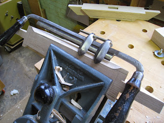
I went to visit Patrick Leach when the hay rake table was still on the drafting board. A draw knife was on one of his monthly tool lists, with a chamfer guide, and the guide really caught my eye. (I still have to tune up the knife I bought from Patrick. This draw knife was ready to go, so I swapped the chamfer guide over.) The guide has two sides, which is normal, but also has a keeper on top, to hold the setting when it gets moved or removed. I moved it around on the knife a fair amount, so that keeper bar helped a lot.


There was a learning curve. (In part because Patrick had clamped the guide onto the knife upside-down.) A draw knife is a pretty dynamic tool: It gives a lot of feedback, and responds best to adjustments made on the fly. And the guides are designed to function accordingly. They're not designed to turn the knife into a chamfer plane. But they do allow a more controlled introduction of the tool to the material, to make it easier to take thin, chamfer- width shavings with the knife. And they do limit the depth of cut, like a chamfer plane. After a while, I was roughing out with the bare side of the knife, and using the guide to take the last few strokes that would leave a nice, uniformly cut facet.


Once I started to get the hang of how the guide works, I also found that it could steer the knife into and through the stop-chamfers, too. The knife is a visceral tool to begin with, but this particular operation felt more instinctual than I'd've thought. It also made layout a lot easier. Initially, I'd drawn out the edges of each chamfer with pencil lines, and traced the curve of the stop chamfers with a fender washer.  But once I understood that the guide would help to shape the stop chamfers, as well as define the chamfer width, nothing more than a tick mark to indicate each end point was necessary. That was a huge time saver.

The more I read about hand tool methods, the more I'm starting to understand just how efficient they can be... and how much thought and effort had been put into making them more so. North Bennet gave me a solid grounding in the fundamentals of hand tool woodwork. But there's a big difference between cutting fine joinery in school, and doing daily battle with dead trees for a living. This particular setup gave me a good long glimpse into a world where push-button woodworking didn't exist... but neither did the time to reverently commune with the wood, or relish the shavings that spill slowly onto your basement floor. This is not the tool of a hobby woodworker.


I had a fair idea when I started the table that I would want to make more furniture like this. And I was right. I'm very handy when it comes to jiggery and precision machine work, and that's where I'll save a lot of my build time. But the opportunity to spend a few hours working and sweating with a draw knife isn't typical of a lot of the other work that I do, and the hand-hewn, burnished surface left behind by the knife isn't either. It's that last cut with the tool that Brian was talking about.

And, it's enjoyable. If I can build more furniture that's big and visceral, like these tables, I'll be a really happy guy. It's worth two weeks of dust and noise to get to a couple of hours of quiet, sweaty, focused work.


Tuesday, December 3, 2013

Using the French chair maker's vise on the hayrake table.


Using 80-20 for most of my jigs saved me a lot of time, but I still needed a fast way to cut shoulders on the 45 degree tenons. Given that it was only one table, it didn't make sense to me to spend a lot of time engineering a way to treat it like a production run. So, I used the French chair maker's vise that I built back in July of 2012:


It's really simple to use. The top surface is reference-flat. The material is clamped lightly in the vise, and the shoulder line is lined up with a gauge stick that's set to the height of the saw blade in a side-cutting saw that's also part of this arrangement. Once everything's in alignment, the material is clamped, and the saw cuts both shoulders to be in exactly the same plane. Clever, simple, efficient. Gotta love that...


 SO how accurately does it cut? Very accurately, as long as the gauge stick is right on, which is the current problem. As pretty as this picture is, I actually need to make a new gauge stick. The tenon sticks up above the vise, I'm actually cutting on the wrong side of the line. The joints all came together fine, but the tool should be working more accurately than this. (To be fair, the blade was pulled out farther than normal for these shoulders, so there may be some error introduced there, but even still... I need to give this some attention.)


Clean shoulders will make or break the look of a mortise and tenon joint, so they have to be done right. For this particular table, this was the most efficient way to get the job done that I could think of. For multiple tables, I might set up something on the table saw (if it was set up, which it's not, yet) or with router templates. But for one table, (8 angled joints) the chair maker's vise is such a quick and intuitive tool that it just made all the sense in the world to cut the shoulders that way.

Joinery's done... chamfers are next. 

Sunday, December 1, 2013

80-20, jiggery, and my foray into building a hay rake table


As I continue to unpack the shop, daily life and parenthood hurtles on in a mildly controllable fashion. Among other things, I had a commission for a hay rake table, made with reclaimed wood, and the client wanted it for Thanksgiving. That, and I still haven't had time to actually hook up the table saw and dust collector, so no table saw was used on this project. Given the need to work quickly, I decided to skip my normal habit of making 'serious' jigs, and worked with a few pieces of 80-20 aluminum that I'd recently unpacked.

If you're a push-button, store-bought jig woodworker, more T-track won't really help you much. If you've been building jigs for a while, and you need a fast way to make new jigs in a flexible way, this stuff is a game-changer. Yes, you can make any of these jigs with wood, MDF, plywood... but there's a lot more drilling, cutting, installing T-track, etc... and at the end of that exercise, you're the proud owner of a dedicated jig that will need periodic recalibration or rebuilding. That's a big investment in time, and an investment in materials that you won't get back. Building these jigs was fast. And when I was done building the table, the original extrusions were in exactly the same condition, and I can use them again for more jigs. THAT'S a big deal.

Fast, flexible, with minimal waste? And not having to break down sheet goods? Yeah, I'm impressed. And I can tell (gut feeling) that I'm just getting my feet wet right now.

Jigs need to position and hold the material in place, and in some cases guide the material past a cutter. Using nothing more than a few carriage bolts, a couple of Incra clamps, and some blocks of scrap wood, I was able to throw together some pretty decent production jigs in a very short amount of time.


Drill press fence for drilling out mortises in the legs. The fence is simply bolted to the table, (holding the plywood surface down, too) the block is held on with a simple 1/4-20 t-track bolt. (The oval-headed kind, not a hex bolt.)


 Stop fence for the band saw, for cutting tenon cheeks, and stopping at the shoulder line. Held onto the band saw fence with Incra clamps.


 Cross-cut fence, and stop fence, for cutting shoulders. I also used this setup for cutting parts to finish length, since some of them (like the legs) were just too big for the track saw to handle. The black extrusions have larger tracks, and use 5/16" carriage bolts.


 Support and stop for drilling out the 45 degree mortises in the stretcher assembly. Again, just bolted to the table. There were moments when I needed the Incra clamp to be moved back, so that I would have space to clamp the material to the extrusion with an F-clamp. Thankfully, there are 3 tracks in the faces of the aluminum, so moving that clamp was very easy. +1 for an easily modified jig...


Cutting the 45 degree mortises in the long stretcher. I did have to bolt on an extended L-shaped block, but it was a very easy thing to do. (By the way, these are the mortises I was working on when I started using the 3-pound hammer.)

As the deadline loomed larger, I quit stopping to take photos. But I also used the extrusions that hold my router table to mount a positioning block to adjust the router table fence more easily and accurately. More on that some other time...


Tuesday, May 14, 2013

More on sliding dovetails


The whole point of making the dovetail plane was to use it on this particular job: 4 large, fixed shelf bookcases. The carcases are single-plank wide cherry, with a finished dimension of around 16".

I used the same technique I'd used on the small footstool to do the joinery here, but with 24 joints to cut in total, (4 cases, with three shelves, 2 joints per shelf) I got a lot more practice, and a little more understanding of the process, to boot.

To make the process faster, I actually ran half of the joint with the same router I used to run the grooves. I did the final fitting of the top side with the plane. I have some funky Festool attachments that allow me to do this, but I'm sure it could easily be set up on a router table, too.

Fitting the joint, first step was to clamp the board down flat, and start working the end of the board. The goal is to have joints that don't have gaps showing at the front. Gaps can always be filled, but I like it better when I don't have to. I started the process with calipers, trying to match up the male end of the joint to the female end.


Eventually I just moved to fitting the ends of the joint to the case. That is, plane the front to fit the front of the case, and plane the back to fit the back, and then work the mid-section until the board slides home. It's important to note that the board has to be flipped for this, because the left side has to be fitted to the left side, and the right side has to be fitted to the right side, before the board is actually able to slide all the way in. The idea is to get that part fitted first, and then leave it alone.


You can see here that the fitted boards are not all the way in. This is done on purpose. Because the joint will wedge itself in place when it's glued up, wedging everything together now isn't really helpful... you'll just have to beat up the work to get that board back out. So, getting the board to slide basically to that last inch or so is pretty typical. 

 On the clamp in the photo, I encountered a couple of times where the boards had started to bow on me. It could be because a few days had gone by since I'd milled them down, cut dovetails, etc, and they'd moved a little bit. It could be because the wood reacted slightly when I ran the dovetail grooves. I'm not entirely sure. I know that some folks insist on doing carcase joinery the same day the wood is milled, because it helps to stabilize everything, and keep it in plane, but with 4 cases to do, with the width of the material, that didn't really seem like an option for me.

That said, there were a couple of the shelves that were slightly cupped. (about 1/16"- 3/32" across 15.5") I figured it would be fine, in the long run, because it would be held flat in the case, and would stabilize over time. But now, I think that doing final milling before fitting this kind of joint makes sense. Clamping a board flat while you plane it, AND fit it, AND try to do assembly is a lot of extra work. Working with flat stock is much easier. And assembling it is easier.


Last word of advice: be SURE to get those boards in to that last inch. I got sloppy on one that was slightly cupped... I figured 2-3" was fine, that the cupping would flatten out, and everything would be fine. This is the part where I confess to the fact that it took 2 I-beam clamps, with pipes slipped over the handles, to crank that shelf into the case all the way. It creaked loudly, like an old door, for about 5 minutes while it slowly shifted into place. I was sweating bullets the entire time, thinking that for sure, the thing was going to explode.  Only push in that last inch.


Sunday, April 14, 2013

The new dovetail plane in use


I'm in the middle of building a set of bookcases, which were the reason for building the plane. But, I think it's important to understand a technique before going ahead and using it on a finished piece, so I decided to make a small footstool for my wife to use, while nursing our son.


Once the lumber is milled up, the first step is to cut the female part of the joint. I ran dados on the top of the stool first, and then brought that part to the bench to use a router to shape the dovetail part of the joint. I used a simple clamping router fence to do the job. The first pass was square to the board. The second pass was laid out to be square, and then the fence was offset by 1/16" on the back end, to make a tapered socket.


The next step was to cut the male part of the joint, and fit each to their corresponding socket. The first one went in pretty well.


The next thing I learned was that it's important to lay out what end of the board is what, so that you don't make a stupid mistake when fitting the joint. 


I trimmed the 'legs' back, and cut the joints again. This time, I laid out the joints with a simple circle, to let me know which side was to be tapered, and on what face. For this stool, I don't think it would be critical. For a bookcase, it's a different story. The finished parts:


Between milling the boards, cutting the pieces, routing the grooves, and cutting the joinery twice, the whole thing, start to finish, was still done before lunch, which isn't too shabby. Next step is to fit the joints for the shelves that will go into these cases:


On making the dovetail plane:


Sunday, February 10, 2013

Converting a Skew Rabbet Plane to a Dovetail Plane, Part 5


For the nicker, I had to do some head scratching. Vintage models use a wedge to hold nickers in place, but I didn't feel like fitting a wedge. And, the alignment issue was also on my mind. What I finally decided on was a pair of hex-key set screws. One comes through from the other side of the body of the plane, just at the bit of the nicker. The other is about 3/32" above it, tapped into the metal plate on the side of the plane. The lower screw allows me to align the bit with the side of the plane. The screw through the plate clamps the nicker in place.

The blade required some fine tuning at the wet grinder to get the angle just right, but it sharpened up just fine. After that, I put everything together and made a few test passes.

When I resoled the plane originally, I made a very tight mouth and throat. But because the shavings are cross-grain, they break off pretty easily, and not only is the support of a tight mouth not really needed, but it jams up pretty quickly. So, I opened it up. Because the blade is basically plowing out material, and not leaving a final surface, I'm ok with this. (I'm more worried with keeping the shavings flowing, than how finely they're being cut... this is intended to be a production too, despite the fussiness I've been putting into it.)

After that... well, that's pretty much it. I made a few more test passes with the plane, and it worked like I'd hoped. So, I gave it a good coat of wax, and played around with it for a while. Next week I'll get to put this tool to work.


Read Part One.
Read Part Two.
Read Part Three. 
Read Part Four.
The Plane In Use.

Friday, February 8, 2013

Converting a Skew Rabbet Plane to a Dovetail Plane, part 4


There are two basic functions that are critical to the proper operation of this plane. The fence needs to guide the cut, and the plane needs to make the cut.

The fence must reliably reference off of the end of the board. A lot of the most obvious work to date has been to accomplish this. The last remaining piece required to make this work is to drill holes in the body of the plane to install some wooden pieces to clamp against the arms of the fence, and some brass inserts, to allow the thumbscrews to drive those wooden pieces down. I used a dowel centering jig, some long brad point bits, and some stop collars to accomplish this.


The cut will be made in two steps: The nicker will score the wood ahead of the blade, establishing the shoulder, and the blade will plow out the waste. To do this properly, the nicker needs to be aligned with the side of the plane, the blade also needs to conform to the shape of the body, and the throat needs to allow the waste to clear. The nicker will be covered in the next entry.

To shape the blade, I needed to know where the edges needed to be. Because the sole used to be square, and because the sides of the plaen used to be wider, there was a lot of shaping that needed to be done. I coated the back with black magic marker, and scribed with an iron from a block plane. I used an 8" slow speed bench grinder to get close to the line, and finished up with a wet grinder. I started with the bench grinder because it's fast. I switched to the wet grinder because the blade comes to a point, and I didn't want to burn the temper out of the blade.


Thursday, February 7, 2013

Converting a Skew Rabbet plane to a dovetail plane Pt 3: New nicker


Because the plane is designed to go cross-grain, it needs a nicker.

Because I didn't have one, I needed to make one.

I spent the better part of half a day cutting and filing this particular bit out of a piece of O-1 tool steel that I had kicking around in a drawer somewhere.

(Yes, I happened to have tool steel kicking around in a drawer. I'm aware that this is possibly not typical behavior. I live with it.)

At that point, I had to dig out my notes from a class that I took with Larry Williams back in 2005, covering heat treatment.

I used a (borrowed, but they're not too expensive) Mapp gas torch to heat treat the bit on the nicker. I also found out the hard way that there's a reason to do this on fire brick, as opposed to bare concrete.

Anyway, the notes say, heat the tang to black. Then heat the bevel side of the bit to cherry red, flip over, continue to heat until spots of flux appear on the surface of the steel. Then quench in oil, stirring the oil with the steel for about a minute or so, holding the piece vertical, to avoid warping.

After that, the steel is hard, but brittle. So, the next step is to temper the blade by baking at 350 for at least an hour. That should soften it up enough to make it usable.

So... yeah. I made a heat treated blade for my dovetail plane. There's a little bit of the beginner in me that's squealing in delight. It may not be a major accomplishment on the grand scale. But it's not something most folks get to do every day, either.

Read Part 1.
Read Part 2.
Read Part 4. 
Read Part 5.  
The Plane In Use.

Thursday, January 24, 2013

Converting a skew rabbet plane to a dovetail plane, part 2


This is where I left off: A plane body, a fence, and two posts. The posts are actually installed backwards in the photo: At one point, I'd considered making a bridle fence, which would have the posts fixed in the plane body, and sticking through the fence. But once I'd cut out the escapement, I realized that wasn't really an option anymore, so they'll be fixed in the fence instead. Some projects are like that.

I turned down the posts to fit on some brass ferrules. The plane body will have thumb screws to hold the setting, and fine adjustments will be made via mallet taps on the posts. Ziricote is hard, but brittle, and splintering can still happen, so I figured the ferrules were a good idea.  Once that was done, I cut a notch in the other end of each post for a wedge, and I epoxied the brass ferrule onto each post.

The fence was the next thing that needed work. The purpose of the fence is to define the length of the dovetail tongue on the end of the board. To be able to do that, it needs to extend underneath the plane. So, I milled another piece to mount onto the bottom of the fence that I had so far, and mounted it with glue and screws.

After that, it was back to work on the plane body. I started by planing the new sole to be flush with the plane body. The next step was to cut a dado for the nicker that I'll need soon. Then I cut through the sole, and shape the bed and the throat, so that the iron could be re-inserted, and would bed properly. I did this mostly by paring carefully with chisels, but final tuning was done with files, for a reasonably tight mouth. At this point, the body was back to 'normal,' and ready for the rest of the conversion.

I decided to add a steel plate to the side of the plane body. Ziricote is pretty durable, but I want to do everything I can up front to prevent wear at the sharp edge of the sole. For a dovetail joint to come together cleanly, that inside corner really needs to be sharply defined. Most of that work will be done by the nicker and the iron, but the edge will be subject to a lot of wear.

Fabricating the plate was a pretty involved process, all things considered. The plate needed to be flattened and gauged. (Made even in thickness) A rabbet had to be cut into the side of the plane body to let in the plate, and holes must be drilled and counter-sunk for mounting. Once the plate's mounted position was established, the bed and throat were laid out on the plate, cut, shaped, faired to the plane body,and a slot cut and filed for the nicker. Note the Emmert is turned around so I can use the metal working jaws... The ability to tilt and turn the vise and work at funny angles was a huge help.

On the list of things yet to do, the dovetail bevel must be filed onto the edge of the plate, and faired to the sole of the plane. Once the sole and the side of the plane have been fully defined, I need to regrind and sharpen the iron, and make the nicker. I also need to drill and install the inserts for the thumb screws that will hold the fence in place. This includes inserting wooden pieces that will press against the posts; I don't want the metal screws to do any damage. At this point, with a working fence, iron, and nicker, the plane should at least be functional. Lastly, I'll clean up and finish the plane.

Read part 1.
Read part 3.
Read part 4. 
Read Part 5. 
The Plane In Use.


Wednesday, January 23, 2013

Converting a skew rabbet plane to a dovetail plane, Pt 1

The job I'm working on right now calls for tapered sliding dovetails. I know there are ways to cut those joints by hand without a dovetail plane, but those methods seem tedious, and I don't have time for that. And I know there are ways to cut them by machine, but those methods don't appeal for one reason or another, mostly because they seem overly fussy, and time consuming.

Truth be told, I could probably have figured out the machine method in the time it's taking me to do this conversion. But I've wanted to add this method to my arsenal since I saw John Reed Fox demonstrate it in a Japanese tool class that I took at the Center for Furniture Craftsmanship, back in 2005. John had his assistant cut the tapered dovetail groove with a router while he was explaining how the plane worked, and when the assistant came back, it took him about a minute to fit the mating board, with the dovetail plane. I was impressed by this, both because it was very cool to watch, and because it was clearly a very efficient way to put a carcase together. But, fast forwarding back to me planning out my current project, Japanese versions of the plane would cost me serious money, and I had this plane on hand. 

Well, that, and fixing up the Spiers plane has given me a real tool-making yen. Yeah... like that's gonna help me focus on my bench work. :-P

Side note, before I proceed. I've gone through phases in my woodworking where I really idealized the purity and (BANG BANG BANG) silence of hand tool woodworking. And I've seen people who know what they're doing demonstrate that it can also be a very efficient way to get things done, if you use the proper methodology and mindset. So my inner purist is laughing his ass off at the fact that I'm using a router table, a table saw, a power planer, a drill press, and a band saw, all to make one measly hand tool.

The photo up top is a 7/8" skew rabbet plane that I bought at an antique shop in Corning, New York, about 6 years ago. I'd intended to get it up to 100% and use it more, and had gone so far as to patch the front right corner, and laminate a rosewood sole onto the thing. As antique wooden planes go, it's not too bad, but had definitely seen some hard times. It was pretty heavily worn, and was shorter in the front than it was in the back. It had a few nail holes in the side, and in the sole. I'm guessing that a former owner used it very regularly, and at one point, scabbed on a fence, or a new sole. There were also nail holes on the side of the plane body, so maybe it was a fence. The factory didn't use quarter-sawn stock, so the growth rings are parallel to the sides, and not the sole, as they should be, so I'm guessing it wasn't a premium model anyway. (Or, maybe the factory had simply stopped caring) Issues aside, there's plenty of length on the iron, and the wedge fits well, so I figured it was worth holding onto.

First things first, I wanted to start with a straight, square, and flat plane body. Like I said, it's not quartersawn stock, so it wasn't as flat as I'd like. I didn't want to take off too much wood if I cold help it, so I flattened one face by hand. I ran the other face through a power planer to get a parallel face, taking very, very fine passes. One side effect of this was to make the iron too wide for the body. This is fine, though, since the iron's going to get reground anyway. I also cut off the rosewood sole, and cut the sole to be parallel to the top. I needed to cut the sole at an angle, since this is going to be a dovetail plane. Bearing in mind that I plan to use the plane in conjunction with a router, I made an angle gauge block with a router bit that had the angle that I wanted, and I used this to set the table saw blade angle. So, I now had a decent blank to start from.

One of the other functional parts of a dovetail plane is a movable fence to gauge how far in the plane will cut. I bounced around a few ideas on how I wanted to set it up, and settled on a fence that looks a little bit like a plow plane fence. To mount this, I needed two posts. I made these on the lathe out of ziricote, because I had some kicking around, and I was feeling fancy. The next step for the plane was to drill holes for the posts, but because the holes in the plane and the fence must match perfectly, I wanted to drill them both at the same time. So, I milled a piece of beech for the fence, and drilled both fence and plane body at the same time. Once that was done, I cut an extension of the escapement through the fence.

The last part of the plane for this step was to laminate a new sole onto the plane. For this, I went again with ziricote. It's related to rosewood, so it's nice and dense. I wiped it down with mineral spirits, and alcohol, and epoxied it to the sole of the plane. Because the sole is beveled, clamping things up can be a challenge, the sole will typically slide to one side. I put some wire brads in the plane body, and clipped them down so that they would bite into the sole, and not let it slide. The sole was milled over-size, and will be planed down when the epoxy has cured.


Read Part 2.
Read Part 3.
Read Part 4. 
Read Part 5. 
The Plane In Use.

Thursday, December 27, 2012

The Dremel as a router


I spent a lot of time inlaying butterfly joints in the slabs this past week. It's a lot of material to remove, and this project has been lagging, so I decided to go with the less traditional methods of waste removal. I drilled out holes with the cordless drill, and then proceeded to handle waste removal with a Dremel tool mounted in the router base that's made by Stewart MacDonald. The butterfly joints go pretty deep, so I went with one of the high speed spiral bits to help handle trimming, since the cutting edge is full length, and they're long enough for the job.

As a hand tool purist, I would be disgusted with myself if it didn't feel so much closer to a hand tool in use than a regular router does. It's slow and steady, pretty controllable, and because it's underpowered, (and because it was cutting through an inch of walnut) it offered more tactile feedback than a regular router would: A full-strength router might buck just enough to let you know it ruined something as it goes by, but not necessarily. So I'm pretty happy with this setup.

There's only one real problem, and it's the reason the ear muffs are in the photo. It sounds almost exactly like this:


Tuesday, July 5, 2011

Hand plane use in a modern shop


Last week I found an example of one of those times when nothing else will do but a traditional tool.

The curly maple for these tables is very curly. But the larger piece was a little bit wound.

We don't have a functioning jointer that's large enough for this board, even if it wasn't highly figured. And I'm not dumb enough to shove the thing through my DW planer and hope for the best. We do have a drum sander. It's not great, but it works well enough. Like thickness planers, what you put in, is what you get out... only thinner. I needed to flatten one face of the board before the drum sander would make a parallel flat surface. So I turned to my hand planes, and a couple of T-track scraps to use as winding sticks.

Most of my planes are bedded at 45 degrees, and they made for a lot of tear-out in either direction. But then I pulled out my high angle smoother, which is bedded at 50 degrees, started working at an angle (as opposed to in-line with the grain) and found the wood to be a lot more cooperative.

A smoother (short-ish plane) isn't what most folks would consider to be the ideal tool for jointing. Something longer would be called for, etc. This is true, but even with that knowledge, the smoother worked well enough. I just wanted to take the wind out before going to the drum sander, without getting a lot of tear-out. And it worked just fine for that. It took me a good hour or so to get this particular slab under control... and that was just planing down two high corners, so I could take it to the drum sander.

Happy with the performance of the high angle plane, I sent a quick email to Lie-Nielsen after I was done, inquiring about the rumored 55 degree #3 smoother. I got back the following from Kirsten:

"Good morning, James.

Excellent timing!  We actually just released our 55 degree frog for the No. 3.  It should be appearing on our website within the next week or so.  The cost is $85."

So, for those of you who have been waiting/hoping... they're now available, and will be on their website this week.

Of course, that frog would only help me if I had a L-N #3, so the real cost will be a lot higher when I get there.