In any event, this piece has required so much problem solving that it's eaten up a lot of time. Every time I solve one problem, another one pops up, if not 2. It's resulted in a lot of sleepless nights, staring at the ceiling in the dark, and trying to wrap my head around changing curves and angles, so I have a better understanding of what's going on. Then I have to figure out how I'm going to make the mental image that I come up with come together in the physical world. In theory, this piece will go into production, so refining the process is important. It's expedient to make a few corrections by hand if you're building a one-off piece, but once you get into multiples, the time spent correcting for errors gets magnified.
I've had to re-invent the wheel on cutting circles, which has resulted in this series of entries. I've made a lot of patterns to shape individual parts. There are some 3-way miters that are square, and some that transition into compound curves, that will be visible from all sides, so there's no room for error. I've had to re-examine accurate miter cutting several times over, as well as calibration of angle measurements. (Hence the review of the Shinwa bevel gauge.) And even once I could cut accurately, the first time I cut a test joint, it didn't come together at all. Normal 3-way miters are 45 degree angles, cut at 90 degrees to the surface. But once you move one of them away from 45 degrees, everything changes, and you get compound angles. And again, because it'll be visible from all sides, everything needs to be perfectly cut. Some of it starts to feel like a mathematical proof sometimes, because the ground work needs to be fully developed before it can be referenced in a larger work, and then there's still problem solving to be done on that higher level. The fundamentals must be solid before higher levels can be achieved... and that starts with accurate work.
As always, the devil is in the details. So much effort goes into making everything look clean, so that the supporting elements can fade quietly into the background. But once you get gaps in the joinery, kinks in your straight lines, tearout, etc, the mistakes all stand out like a squeaky clarinet in an otherwise harmonious symphony. You'll notice nothing else.
Back to cutting curves...
----
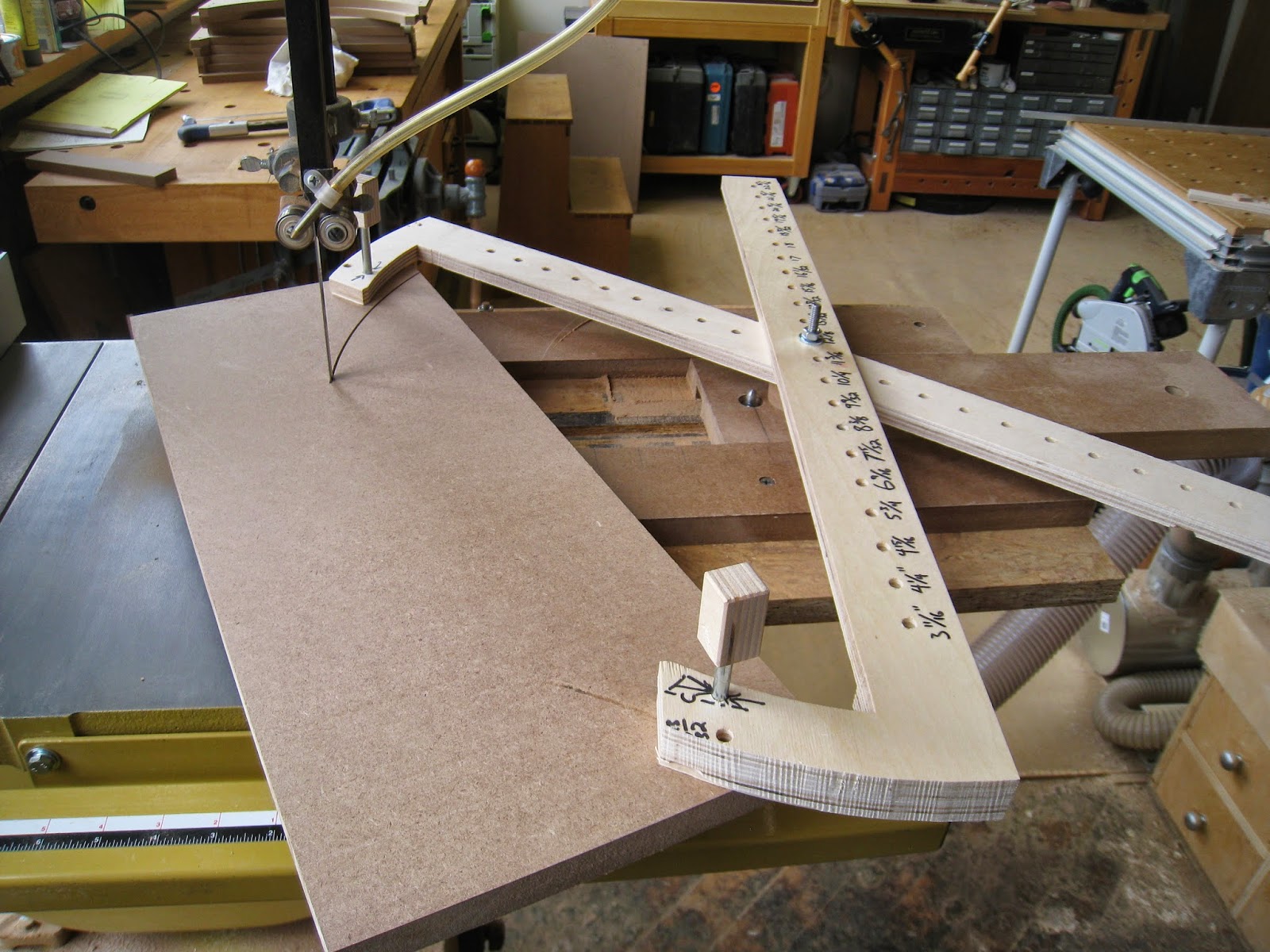
So, this is where we were last time:

In the photo, we have sliding center point jigs for the band saw, and for the router table. A dog-leg scissors jig with pins will mount to a blank, for cutting inside or outside radii, with a center pin that will transfer neatly from band saw to router table. For my next trick, I wanted to use it to make a pile of precise identical parts to use for making a bending form. I figured that would test the system, to see how robust it was.
I'll confess here to being a little too cerebral. Mark wandered over, asked what I was up to, and pointedly remarked that I was doing things in 'long-hand.' And he was right. There are many ways to skin this particular cat, and almost all of them are much more efficient. (Make one master curve, and pattern-rout the rest from that, would be the fastest.) But I wanted to see this experiment through, and see if the long-hand proof would result in something that would save me time down the road.

Using the jig for cutting radii in either direction (inside or outside) is pretty simple. Because the jig has so many holes, it's easy to find a setup that will work. But I realized pretty quickly that mounting pin placement was an X-factor. The holes for the pins are drilled at identical distances from the center, but the distance between pins is also relevant. Once the arc is laid out to locate the mounting pins, you can drill anywhere along that arc. But the chord length- the distance between the two pins- will determine how far into the blank that curve gets cut. Two different chord lengths will result in two cuts with identical radii, but different placement of that cut in the blank. It was one of those details that's obvious in hindsight, but still made me scratch my head for a minute. Since the object is to create a bending form, all of the layers must be identical, so pin placement needs to be the same on all of them.

I laid out the first blank, and set up the pin holes to be exactly the same distance from each side, and from the front edge, and drilled them using a fence and a stop block. Drill, flip, drill, and the result is two holes with identical spacing from each end, and the edge.

To the band saw, and then to the router table...

Initially, I'd used a smooth pin, loosely installed in a hole to hold the center. I switched to a threaded bolt that ended in a smooth pin, because there was slop in the radius with just the loose pin. It only made for a difference of maybe 1/64"- 1/32" from one blank to the next, but for a bending form, everything has to be exactly the same. This was the part when Mark made the comment about doing things longhand, and flush trimming being faster. Obviously, he's right, at this point. But being able to swap parts from one operation to another without having to attach a pattern for flush trimming will save time in production later on.
With the slop issue ironed out, the final stack was just about perfect. There were inconsistencies that I could feel, but they were small enough to fix with a plane. It felt a little bit like cheating, since I was trying so hard to make the the jig accurate enough to not need to smooth anything out, but any play in the pivot point makes inconsistency unavoidable. All things considered, it's still a very accurate system. The fact that I can re-adjust the center point and take a second pass, means I can creep up on a very accurate radius for a master pattern, or on a wooden part. And with the router table, I can make a finished curved surface that's ready for sanding.

-----
Part 3 will go into a little more theory on dealing with radii. The form is a 2 part form, so it will have a mating piece. But cutting that means taking the convex off-cuts from the concave form, with identical but unknown radii, and finding a way to locate the mounting pins to change the radius.
No comments:
Post a Comment